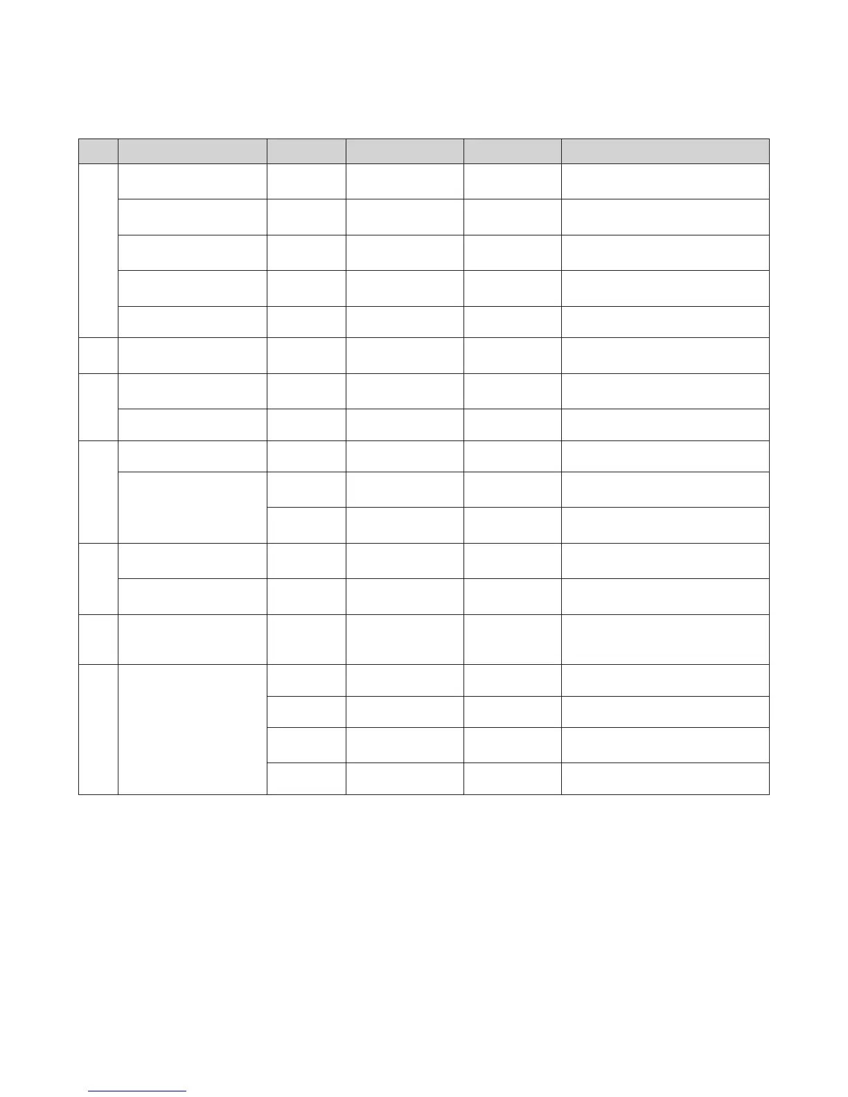
Point Function CN No. Wire Color Normal Value Check
A
Exhaust Thermistor CNJ1 1-2 BLUE-BLUE DC 0-5V
Voltage changes according to
temperature
Heating Return
Temperature Sensor
CNJ1 5-6 BLUE-BLUE DC 0-5V
Voltage changes according to
temperature
Heating Supply
Temperature Sensor
CNJ1 7-8 BLUE-BLUE DC 0-5V
Voltage changes according to
temperature
High
Temperature Limit Switch
CNJ1 13-14 BLACK-BLACK DC 0V Normally Shorted. Confirm RMS voltage
APS CNJ1 9-10-12 RED-BLACK-WHITE DC 5V
B Outdoor Thermostat CNT3 BLUE-BLUE DC 0-5V
Voltage changes according to
temperature
C
Flame Rod CNI1 2 BLACK DC 10uA
Measure the current when the burner is
operating.
Ground Wire CNI1 1 GREEN / YELLOW Check for properly grounded wire
D
Water Pressure Sensor CNG1 4-5-6 RED-BLACK DC 0-5V
Gas Valve
CNG1 2-3 WHITE-YELLOW DC 22-24V
Confirm voltage as the Main Gas Valve 1
is operating.
CNG1 1-2 WHITE-RED DC 22-24V
Confirm voltage as the Main Gas Valve 2
is operating.
E
Dual Venturi CNO1 1-2-4 BROWN-BLACK-BLUE
ON : AC 95-120V
OFF : 0V
Confirm voltage relative to operation
Igniter CNO1 5-7 BLUE-BROWN
ON : AC 97-138V
OFF : 0V
Confirm voltage when the unit is
igniting.
F Power Input CON1 1-2 WHITE-BLACK AC 97-138V
Confirm appropriate power source.
Confirm the fuse.
Confirm the circuit breaker
G Fan Motor
CNR1 4-7 BLACK-RED DC 127-184V Confirm steady voltage
CNR1 2-4 BLACK-YELLOW DC 15V Confirm steady voltage
CNR1 3-4 BLACK-ORANGE DC 0-7.5V
Voltage changes relative to fan
operation
CNR1 1-4 BLACK-WHITE 0-6,700rpm Check pulse

 Loading...