DIAGNOSTICMANUAL
COMPONENTDESCRIPTIONS(THEORYOFOPERATION)
12.1.MAXXFORCE
®
11AND13
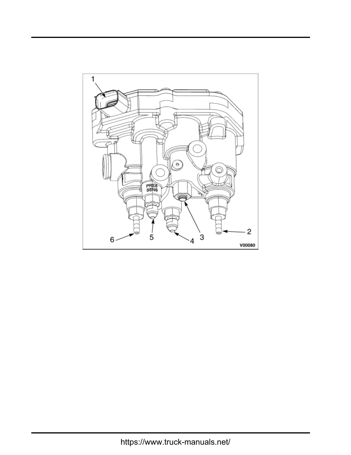
1.Electricalconnector
2.Turbocharger1WastegateControl
(TC1WC)port
3.Vehicleairsupplyport
4.ExhaustBackPressureValve
(EBPV)port
5.Turbocharger1TurbineOutlet
Pressure(TC1TOP)sensorport
6.Turbocharger2WastegateControl
(TC2WC)port
Figure35ACVAssembly(MaxxForce®11and13Engines)
AirControlValve(ACV)Assembly
TheAirControlValve(ACV)assemblycontainstheLowPressure(LP)turbochargerwastegatecontrolport,
HighPressure(HP)turbochargerwastegatecontrolport,theExhaustBackPressureValve(EBPV)control
port,andtheTurbocharger1TurbineOutletPressure(TC1TOP)port.Althoughthesecomponentsareintegral
totheACV,eachcircuitiscontrolledbytheECM.TheACVcontrolscompressedairforeachcontrolvalve.
Theairsupplyportisconnectedtothevehicle'sairsystem.
ProperoperationoftheACViscriticalinpreventinganaftertreatmentconcern.WhenanACVconcernis
present,itwillcauselowengineperformanceanddirectlyeffectaftertreatmentsystemoperation.
138
https://www.truck-manuals.net/
 Loading...


