INSTALLATION/ SERVICE MANUAL
INSTALLATION/ SERVICE MANUAL
27
28
INSTALLATION INSTRUCTIONS
YAMAHA G29 DC to AC Conversion cont’d
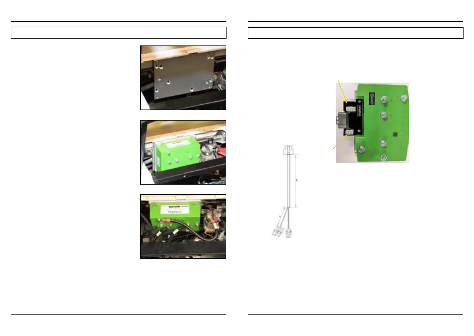
4. Install G29 Mounting Plate
• Align plate with existing holes (where OEM controller
was fastened) and fasten with screws (Fig. 4)
5. Mount Controller
• Install Navitas AC controller (Fig. 5).
• Connect B- from battery, B+ from solenoid and motor
phase cables to U, V, W (use new cable provided as
‘W’ and re-use the 2 existing motor phase cables from
A1=U, A2=V) to the controller (Fig. 6)
6. Motor Conversion
• Remove motor phase cables A1, A2 from motor
• Remove and DISCARD field cables (F1, F2)
• Remove DC motor
• Install Navitas AC motor
• Connect new speed sensor/motor temp harness to
motor
• Connect motor phase wires from controller using the
removed A1 and A2 wires and the included wire (U =
U, V = V and W = W)
• Check cabling to make sure U, V, and W match
exactly from motor to controller
7. Connect OEM Harness to Adaptor Module
8. Install On-The-Fly Programmer (optional)
• Install OTF (optional) (see install description in RXV
INSTALL instructions, p12)
• Connect OTF to the adapter module
• Zip Tie loose cables
9. Test Installation
• Lift rear wheels
• Reconnect battery pack
• Put in “RUN” mode
• Turn key on
• Put in “F” for Forward
• Press on throttle to activate wheels
Fig. 4
Fig. 5
Fig. 6
Pinout for Controller
INSTALLATION INSTRUCTIONS
YAMAHA G29 DC to AC Conversion cont’d
Diagrams and other updates available at:
NavitasVS.com/support
P1: NA
P2: Charger Interlock In
P3: Main Solenoid Out
P4: Reverse Buzzer Out
P5: +5V PF
P6: GND Poly
P7: Throttle In
P8: Key In
P9: Reverse In
P10: Forward In
P11: Foot Switch In
P12: Logic Power In
P13: Logic Power In
P14: NA
P15: +5V PF
P16: GND Poly
P17: NA
P18: NA
P19: NA
P20: NA
P21: NA
P22: NA
P23: NA
P24: GND Poly
P25: +5V PF
P26: NA
To Navitas AC Motor Adapter
PN: 40-000580
Navitas AC Motor Adapter
40-000580
To AC Motor
Speed Sensor
Temperature Sensor
2-POS
282080-1
4-POS
282088-1
10-POS Molex
39-01-2100
P1: Motor Temperature In
P2: Analog GND
P1: +5V PF
P2: Encoder B In
P3: Encoder A In
P4: Digital GND
P1: +5V PF
P2: Encoder A In
P3: Encoder B In
P4: Digital GND
P5: NA
P6: Motor Temperature In
P7: Analog GND
P8: NA
P9: NA
P10: NA
P1: +5V PF
P2: Encoder A In
P3: Encoder B In
P4: Digital GND
P5: NA
P6: Motor Temperature In
P7: Analog GND
P8: NA
P9: Key In
P10: Mot
or Brake Solenoid Release
To OEM vehicle harness
To OTF Programmer
PN: 10-000686
P1: +12V PF
P2: OTF Regen
P3: OTF speed
P4: OTF acceleration
P5: +5V PF
P6: OTF Lock
P7: OTF LED
P8: Analog GND
Navitas TAC2 AC Motor Controller
For Yamaha G29 DC-AC Conversion
Product Model 10-000888-09
8-POS Molex
39-28-1083
26 POS Molex
MX23A26NF1
10-POS Molex
39-28-1103
Module 40- 000632
TAC2 for Yamaha G29
AC Motor Adapter
OTF
Issue Date: 20181219
RES Post may not be installed in conversion model!
Navitas TAC2 AC Motor Controller
for YAMAHA G29 DC-AC Conversion
Product Model 10-000888-09 (440A)
10-000890-09 (600A)
 Loading...

