Qube 300 | Installation Manual
9
Check that the SIM Card is
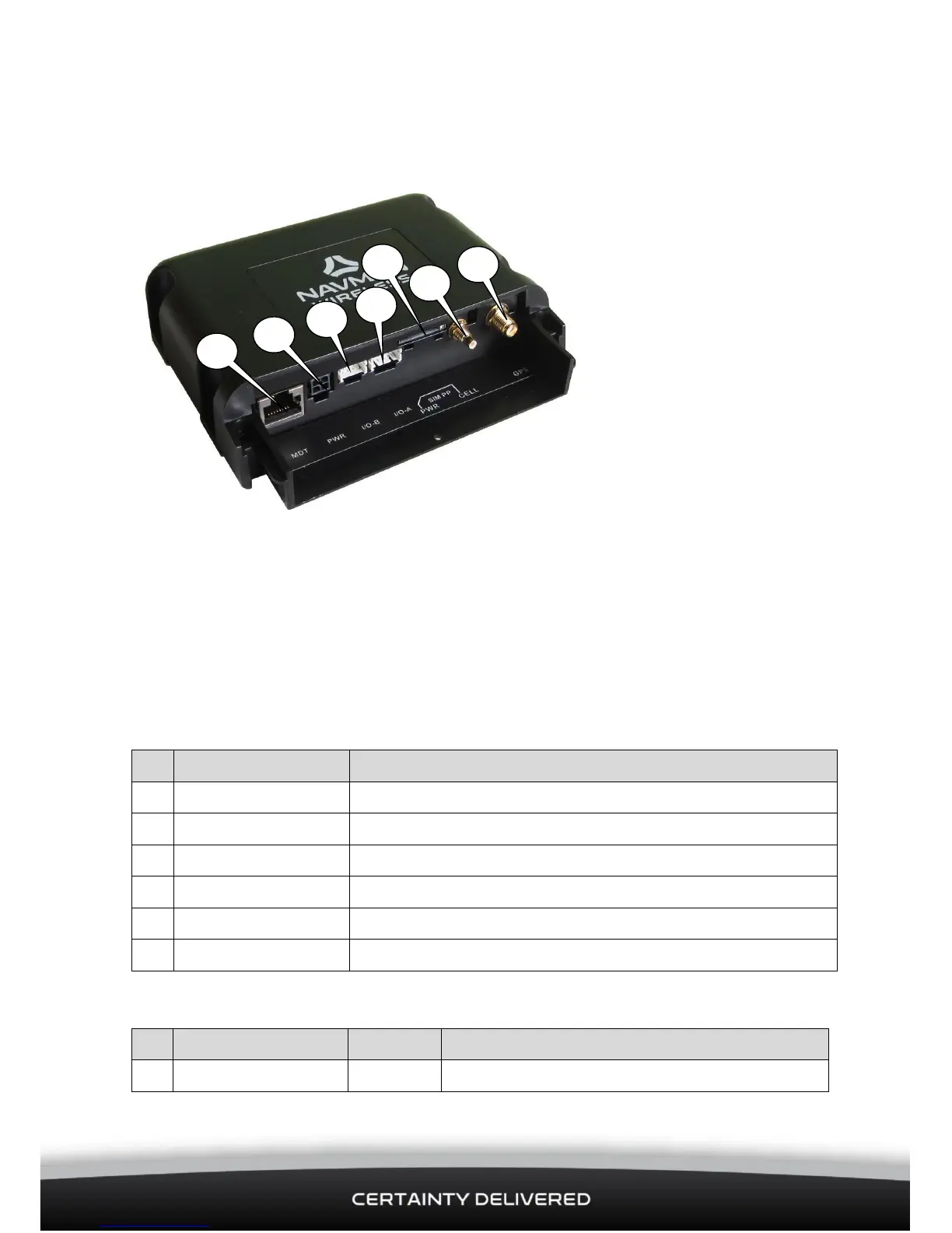
4.3 Connect Any Auxiliary Devices
The Qube 300 has 3 serial ports. Use these to connect to other Navman Wireless devices, such as an M-Nav
or MDT, or to third-party equipment for serial data communication. The Qube 300 also has several digital
and analogue I/O lines which can be connected to external sensors or equipment, using optional I/O cables
as follows:
Connection to the serial port 1 is made through the RJ45 Connector (MDT) at position 1,
8-Way Expansion Connector (I/O-B) at position 3,
10-Way Expansion Connector (I/O-A) at position 4
RJ45 Connector:
Serial Port 1 (Input) Ready To Send Flow Control
Serial Port 1 (Input) Data
Serial Port 1 (Output) Data
Serial Port 1 (Output) Clear To Send Flow Control
8-Way Expansion Connector:
inserted at position 5 (HSPA
units only).
Screw the Cellular Antenna
connector to the CELL connector
connector to the GPS connector
Insert the 3-Wire Power cable
to the 4-Way PWR connector at
If there are NO auxiliary devices or sensors
to be connected, proceed to section 4.5.
If you need to connect any auxiliary
Devices or sensors, proceed to section 4.3.
 Loading...