NDW | We’ll keep you rolling | 12
NDW | We’ll keep you rolling | 13
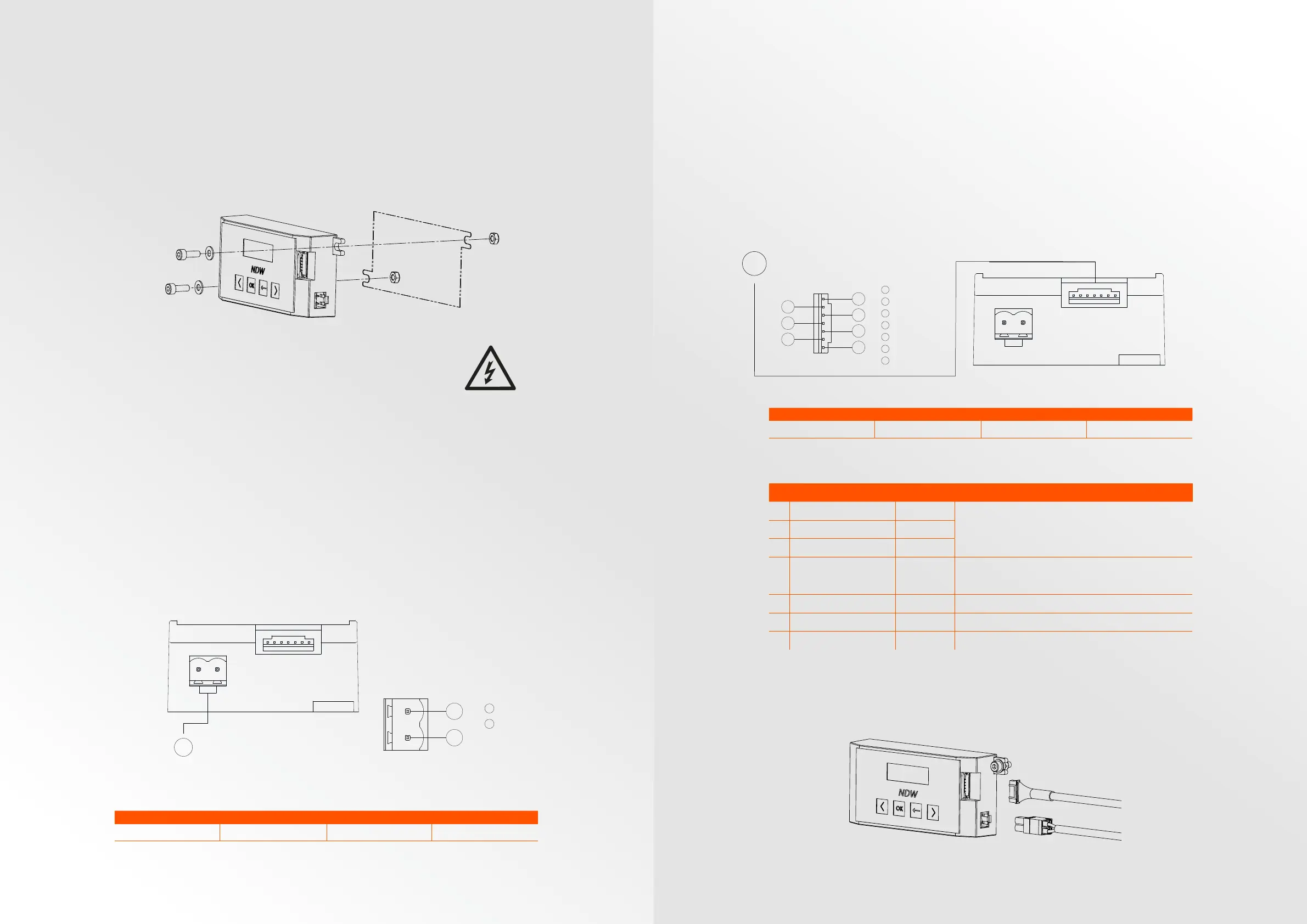
Mounting the controller
• Locate a flat surface to mount the BC50 controller.
• Mark the center for the two mounting holes using the BC50 controller as
a template.
• The precise dimensions and distance between holes can be found in the
dimensions page.
• Drill two mounting holes at the marked spots. Mount the BC50 controller.
• Make sure the mounting surface and bolts are properly earthed.
Electrical installation
Connection of the power
The BC50 controller is powered by an external 24V power supply. Choose
a power supply that is suciently powerful for the number of E-rollers and
their application.
The use of standard NDW 24V power cables is recommended. Order code:
901-CABP24-1-L.
The “L” stands for required length. Available in dierent standard lengths.
Custom lengths can be made on request. A full overview of accessories is
shown on page 27.
The 24V power cable must be plugged into the green connector on the BC50
controller. Make sure the polarity of the power cable is correct.
Connection of the communication cable
The BC50 controller can operate in stand-alone mode by using the integrated
user-interface to control the E-roller. If external I/O control is required, the
communication cable must be connected. Via this cable, the controller can
be controlled with external I/O signals. For example, using a PLC or similar
device.
The use of standard NDW communication cables is required. Order code:
901-CABCOM-1-L.
The “L” stands for required length. Available in dierent standard lengths.
Custom lengths can be made on request. A full overview of accessories is
shown on page 27.
Surface finish:
Deburr and break all sharp edges
NAME
DATE
Material:
3D file is leading
Revision:
Title:
Drawing name:
SCALE:1:1
SHEET 2 OF 3
A3
TvL
TvL
11/09/2019
11/09/2019
Budget_Asm_R01
R01
Weight [kg]:
According to ISO 2768-mK unless
specified otherwise
Drawn by
Checked by
Tolerances:
All units are in mm unless specified otherwise
Remarks
A A
B B
C C
D D
E E
F F
8
8
7
7
6
6
5
5
4
4
3
3
2
2
1
1
Type Connector Cable specification Remarks
24Vdc power cable Phoenix: 1754568
2x1 mm² Use 1 mm² ferrules
Type Connector Cable specification Remarks
Communication cable JST-PHR-7
7x0.14 mm²
-
Power Supply Connection
6
1
24VDC
2
Ground
1
2
1
O / Speed 1
2
Speed 2 / SPeed 3
3
Direction
I/O Connection
1
2
3
4
5
6
7
4
Error
5
Ground
6
Digital A
7
Digital B
5
1
O / Speed 1
2
Speed 2 / SPeed 3
3
Direction
I/O Connection
1
2
3
4
5
6
7
4
Error
5
Ground
6
Digital A
7
Digital B
5
ID Name Type Parameters
1 O / Speed 1 Input
2 Speed 2 / Speed 3 Input
3 Direction Input
4 Error Output
Outputs: ≤ 10mA
“inactive <2V” / “active” > 22V (PNP)
“active <2V” / “inactive” > 22V* (NPN)
*For NPN: requires pull-up at PLC or IO device.
5 Ground Ground
6 Digital A (Not used) -
7 Digital B (Not used) -
24Vdc (PNP or NPN)
Inputs: “inactive” ≤ 3V / “active” ≥ 6V (PNP)
“active” ≤ 3V / “inactive” ≥ 6V (NPN)
All inputs and outputs are galvanically isolated from the external 24Vdc power supply.
Therefore, the ground connection (ID5) must always be connected when using I/O control.
Surface finish:
Deburr and break all sharp edges
NAME
DATE
Material:
3D file is leading
Revision:
Title:
Drawing name:
SCALE:1:1
SHEET 4 OF 5
A3
TvL
TvL
19/09/2019
19/09/2019
BC50_Asm_R02
R01
Weight [kg]:
According to ISO 2768-mK unless
specified otherwise
Drawn by
Checked by
Tolerances:
All units are in mm unless specified otherwise
Remarks
A A
B B
C C
D D
E E
F F
8
8
7
7
6
6
5
5
4
4
3
3
2
2
1
1
 Loading...