NDW | We’ll keep you rolling | 14
NDW | We’ll keep you rolling | 15
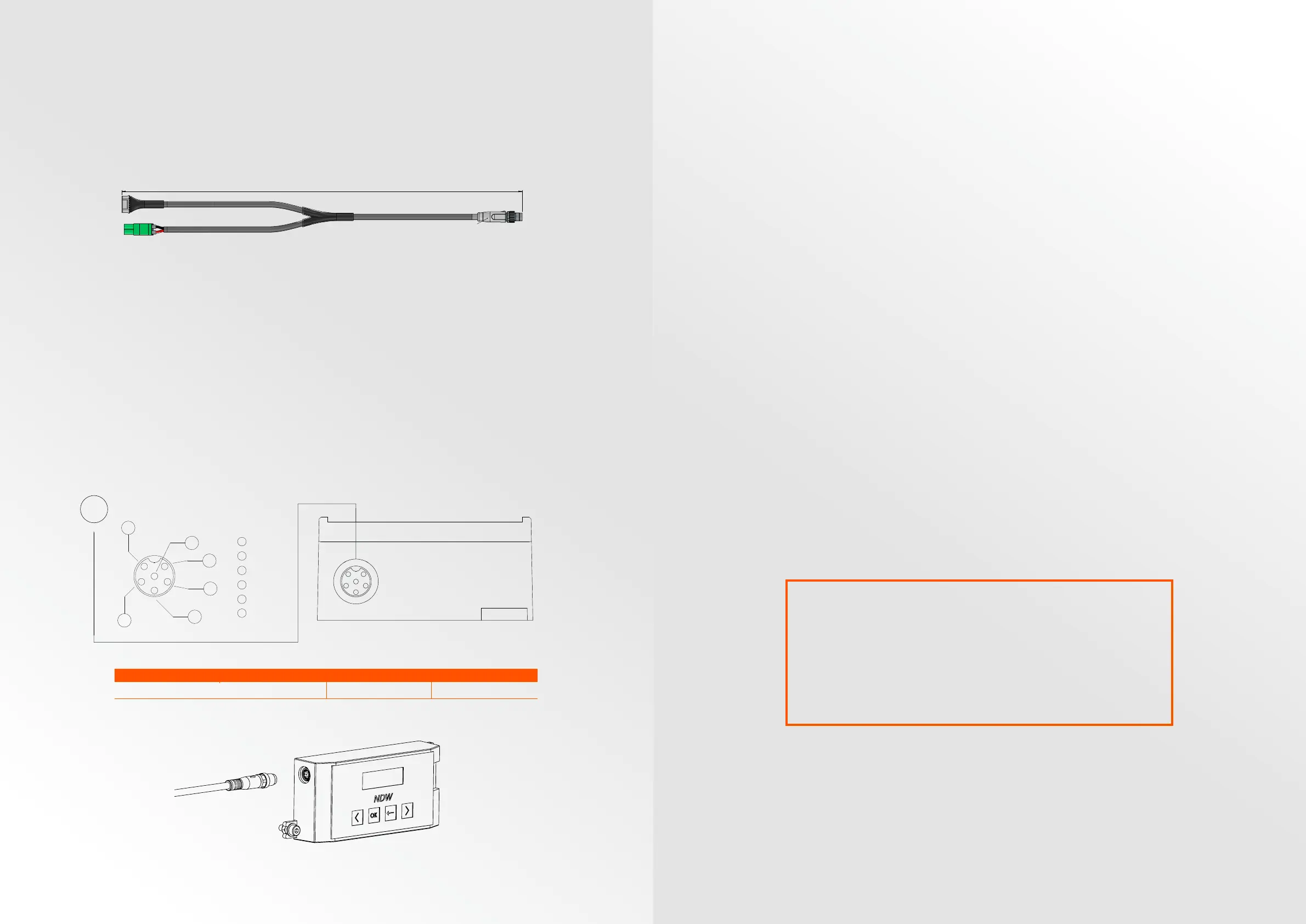
M8-5pin Adapter cable
If desired, it is possible to order an adapter cable that combines the 24V
power and communication cable to a standard M8-5pin connector which
allows for integration with existing electrical infrastructure and control
platforms (i.e. ASI, B&W, P&F, MOLEX etc).
Order code: 901-ADP-B-SC/SN. A full overview of accessories is shown on
page 27. For more information, please contact NDW.
Connection of the NDW E-roller
The NDW motorized E-roller can directly be plugged into the BC50 controller.
Use the screw connection to fixate the cable.
If required, the cable of the E-roller can be extended using NDW motor
extension cables. Order code: 901-CABMOT-L. Only use original NDW motor
extension cables since they guarantee the required ratings.
The “L” stands for required length. Available in dierent standard lengths. A
full overview of accessories is shown on page 27.
NOTE: The total length of the E-roller cable may not exceed 6 meters.
Only connect the E-roller when the controller has no power.
310
Available in two configuration:
- M8 screw connection (901-ADP-B-SC)
- M8 snap-in connection (901-ADP-B-SN)
Pin No. 2
Pin No. 5
Pin No. 3
Pin No. 1
Pin No. 1
Pin No. 4
Pin No. 1
Front view of COM connector
Front view of PWR connector
*Required speed must be set on the NDW controller
Front view of M8 connector
Pin No.
Color
Function
1
Green
Off / Spd 1
2
Orange
Spd 2 / Spd 3
3
White
Direction
4
Black
Error
5
Blue
Ground
6
Red
Digital A
7
Yellow
Digital B
Pin No.
Color
Function
1
Red
24V+
2
Black
0V-
Pin No.
Function (901-ADP-B-SC)
Function (901-ADP-B-SN)
1
24V+ 24V+
2
Direction Direction
3
0 V- 0V-
4
Start/Stop (24V+)
Error output
5
Not Used
Start/Stop (24V+)
Surface finish:
Deburr and break all sharp edges
NAME
DATE
Material:
3D file is leading
Revision:
Title:
Drawing name:
SCALE:1:2
SHEET 1 OF 1
A3
TvL
TvL
30/09/2019
30/09/2019
901-ADP-B
R01
Weight [kg]:
According to ISO 2768-mK unless
specified otherwise
Drawn by
Checked by
Tolerances:
All units are in mm unless specified otherwise
Remarks
A A
B B
C C
D D
E E
F F
8
8
7
7
6
6
5
5
4
4
3
3
2
2
1
1
Type Connector Cable specification Remarks
E-Roller cable M8-6pin screw
6x0.25 mm²
-
1
1
5
6
3
4
2
1 24V
2 Speed feedback
3 Direction
4 0V
5 Speed control
6 Run / Stop
Motor Connection
1
1
5
6
3
4
2
1 24V
2 Speed feedback
3 Direction
4 0V
5 Speed control
6 Run / Stop
Motor Connection
Surface finish:
Deburr and break all sharp edges
NAME
DATE
Material:
3D file is leading
Revision:
Title:
Drawing name:
SCALE:1:1
SHEET 5 OF 5
A3
TvL
TvL
19/09/2019
19/09/2019
BC50_Asm_R02
R01
Weight [kg]:
According to ISO 2768-mK unless
specified otherwise
Drawn by
Checked by
Tolerances:
All units are in mm unless specified otherwise
Remarks
A A
B B
C C
D D
E E
F F
8
8
7
7
6
6
5
5
4
4
3
3
2
2
1
1
INITIAL STARTUP AND OPERATION
Checks before initial start up
• Make sure that the BC50 controller is mounted correctly and that all the
screws have been tightened.
• Check the area around the controller and the motorized roller to make sure
there are no other components creating dangerous situations.
• Make sure that the wiring is in accordance with the specification and
legal directives.
• Check all protective measurements.
• Check if the motorized roller is properly mounted to prevent damage to the
motor cable due to rotation.
• Check the conveyor system and make sure no personnel stands in
hazardous areas.
Checks before operation
• Check the BC50 controller for visible damage.
• Check all protective measurements.
• Make sure there is no blockage of the E-roller.
• Check the conveyor system and make sure no personnel stands in
hazardous areas.
WARNING!
Accidental start-up of the E-roller
Hazardous situation for both personnel and goods. Make sure no
unauthorized persons are near the conveyor before switching on
the power supply.
 Loading...