Description
of
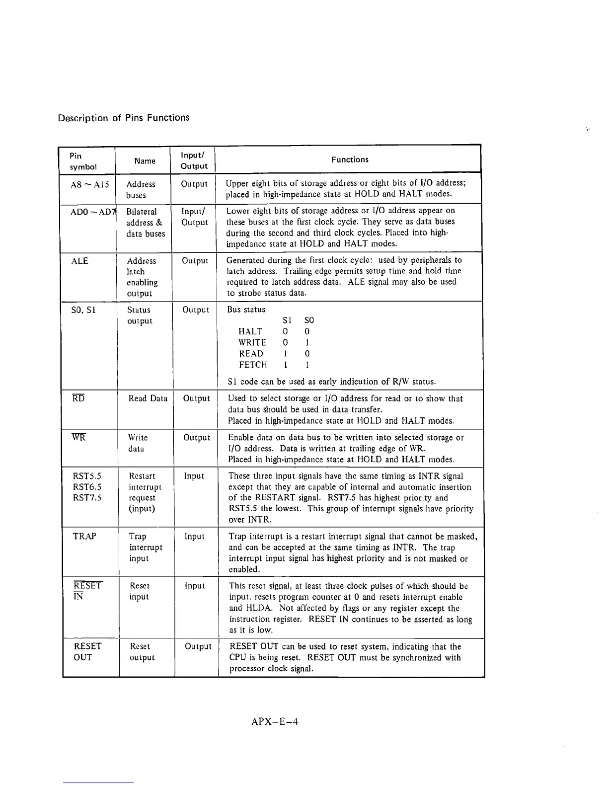
Pins Functions
Pin
symbol
A8
-
A1
5
ADO
-AD7
ALE
SO. SI
Name
Address
buses
Bilateral
address
Sr
data buses
Address
latch
enabling
output
Status
output
Input/
I
Functions
Output
-
RD
-
WR
RST5.5
RST6.5
RST7.5
TRAP
RESET
-
IN
RESET
OUT
Output
Input/
Output
Ou~put
Output
Upper
eight bits of storage address or eight bits of 110 address;
placed
in high-impedance state at HOLD and HALT modes.
Lower eight bits of storage address or
110 address appear on
these
buses at the first clock cycle. They serve as data buses
during the second and
thud clock cycles. Placed into Iugh-
impedance state at IIOLD and HALT modes.
Generated during the
f~rst clock cycle: used by peripherals to
latch address. Trailing edge permits setup time and hold
time
requlred to latch address data. ALE signal may also be used
to strobe status data.
Bus status
S1
SO
HALT
0
0
WRITE
0
1
READ
1
0
FETCH 1
1
I
1
Sl code can be used as early indicution of R/W status.
Read Data
\Yrite
data
Iiestdrt
interrupt
request
(input)
Trap
interrupt
input
Reset
input
Reset
output
Output
Output
Input
Input
Input
Output
Used to select
storagc or 110 address for read or to show that
data bus should be used
in
dara transfer.
I'laced in high-impedance state at HOLD and HALT modes.
Enable data on data bus to be written into selected storage or
110
address. Data is written at trailing edge of WR.
Placed in high-impedance state at HOLD and HALT modes.
These three input signals have the same timing as INTR signal
except that they
are capable of internal and automatic insertion
of the RESTART signal.
RST7.5
has highest priority and
1ZST5.5 the lowesr. This group of interrupt signals have priority
over INTR.
Trap interrupt is a restart interrupt signal that cannot be masked,
and can be accepted at the same
tirnuig as INTR. The trap
interrupt input signal has highest priority and is not masked or
enabled.
This reset signal: at least three clock pulses of which should be
input, resets program counter at
0 and resets interrupt enable
and HLDA. Not affected by flags or any register except the
instruction register. RESET
IN
continues to be asserted as long
as it is low.
RESET OUT can be used to reset system, indicating that the
CPU is being reset. RESET OUT
nlust be synchronized with
processor clock signal.