NECTA SPA TECHNICAL MANUAL “COLIBRÌ”
Service Manual: Colibrì Edition 02-2002 7 /25
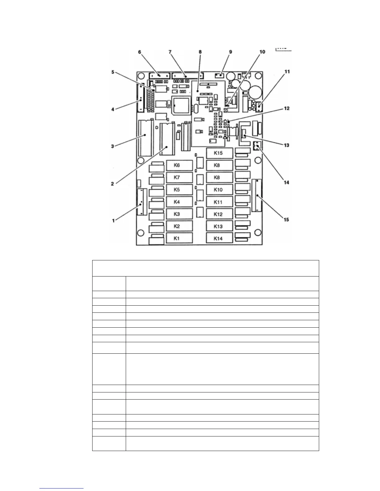
ACTUATION AND CPU CONTROL BOARD
Board components legend
N. Description
1
Connector for 230 V users
2 RAM
3 EPROM
4
Connector for input signals
5 (DL2) GREEN LED (blinking during normal operation)
6
Connector not used
7
Connector for push-button board
8
Expansion boards for payment system protocols (optional); as standard feature the CPU
board controls exclusively parallel-type payments systems
9
Trimmer for boiler temperature control
The boiler temperature is factory adjusted for optimum operation and must not be
changed. In the event of the probe being replaced, the temperature needs to be
readjusted, keeping in mind that the temperature increases by tightening and decreases by
loosening, and each complete turn corresponds to a change of 0.5 °C
10 (DL2) YELLOW LED (Correct power supply to the board)
11
Board power supply connector
12 (DL2) RED LED - When starting the machine it indicates that boiler heating element is
working)
13 TRIAC - boiler heating element actuation
14
Boiler heating element connector
15
Connector for 230 V AC users
16
Relay for actuations (K1 - K15, see separate list page 8)