24
2. TECHNICAL INFORMATION ABOUT FUNCTION
The chain actuator opens and closes the window using a double row steel chain inside a
sheath. Movement is generated using electrical energy that powers a reduction motor
controlled by an electrical device. Windows can be programmed to open and the device
allows chain opening at 110, 200, 300 and 400 mm for Kato, 100, 200 and 400 mm for Kato
Syncro
3
.
When the window returns to start position, that is during closure, the stroke-end uses an
electronic self regulating process with absorption of energy and no regulation is therefore
required. The actuator is produced by the factory with the chain 1 cm out. This allows the
actuator to be assembled without electrical energy powering movement and means that the
window remains closed after assembly. The joint between actuator and support brackets is
quick, requires no fixing screws (NEKOS patent) and allows the actuator to rotate to follow the
track of the chain even on shorter windows.
3. FORMULAS AND RECOMMENDATIONS FOR INSTALLATION
3.1. Calculation of opening / closure force
Using the formulas on this page, approximate calculations can be made for the force
required to open or close the window considering all the factors that determine the
calculation.
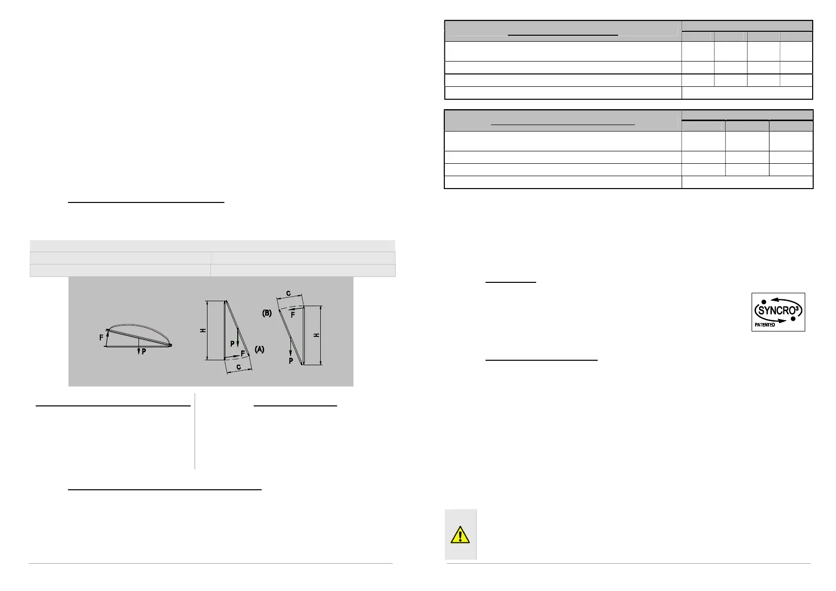
Symbols used for the calculation
F (Kg) = Force for opening or closing
P (Kg) = Weight of the window (mobile sash only)
C (cm) = Opening stroke (actuator stroke) H (cm) = Height of the mobile sash
For horizontal light domes or skylights
F = 0.54 x P
(Eventual weight of snow or wind on the
cupola should be calculated separately).
For vertical windows
TOP HUNG WINDOWS, OUTWARD OPENING (A)
BOTTOM HUNG WINDOWS (B)
F = 0.54 x P x C : H
(Eventual load of favourable or unfavourable wind on
the sash should be calculated separately.)
3.2. Maximum opening according to height of sash
The actuator stroke is in accordance with the height of the sash and its application. Check
that the actuator stroke does not touch the profile of the sash and that the chain does not
exert force on the window frame (measurements in mm).
ATTENTION. For safety reasons the actuator should not be assembled if dimensions are
inferior to those indicated in the table below. In the event that the height of the sash should
be lower, call on the manufacturer to check the appliance.
25
Mode of installation of Kato
Selection of actuator stroke
Light domes, skylights or vertical top hung windows opening
outwards with frontal assembly
150 250 350 450
Top hung windows opening outwards with horizontal assembly
150 250 350 450
Bottom hung windows (motor on frame)
250 450 600 700
Bottom hung windows (motor on sash)
Mode of installation of Kato Syncro
3
Selection of actuator stroke
Light domes, skylights or vertical top hung windows opening
outwards with frontal assembly
150 250 450
Top hung windows opening outwards with horizontal assembly
150 250 450
Bottom hung windows (motor on frame)
250 450 700
Bottom hung windows (motor on sash) Consult manufacturer
4. USE OF ACTUATOR IN ‘SYNCRO³’ VERSION
In the SYNCRO
3
version the actuator has been equipped with the new system patented by
NEKOS for coordinated synchronisation of chain movement. Electronic control of speed is
completely automatic and does not require any external control station: connect the RED and
WHITE cables on the feeder cable to each other (see diagram on page 32).
4.1. Recognition
To recognise on sight chain actuator Kato Syncro
3
pay attention to 3
important differences:
Label with Syncro mark
Electrical feeding cable with 5 wires
Dip-switch on actuator hip with four switches
4.2. When it has to be mounted
Kato Syncro
3
chain actuator is mounted when are necessary two or more attach points
because window is particularly heavy or large and a single actuator doesn’t allow the perfect
frame closure. Please remind that force executed from a single actuator is the same as from
an analogue Kato actuator; so, for example, mounting two actuators the force applied on
frame is double. Frame movement occurs uniformly, synchronized and coordinated without
interruptions and/or speed variations of the actuators. In case of one of the actuators doesn’t
run for any mechanical or electrical impediment, the others stop too, guarantying in this way
frame integrity.
IMPORTANT: when calculating the dimensions of a system with multiple Syncro³
actuators, it is advisable to consider the force of each actuator as 90% of that stated
on the plate.
5. CONSTRUCTION AND STANDARDS
The
and
chain actuators have been
designed and manufactured to open and close top hung windows opening outwards,
bottom hung windows, dormer windows, light domes and skylights. Specific use is
for ventilation and airing of areas; any other use is strongly discouraged, with the
supplier of the entire system in any case retaining sole liability.