28
9. INSTRUCTIONS FOR ASSEMBLY
These indications are for specialised technical personnel and basic work and safety
techniques are not indicated.
All preparatory, assembly and electrical connection operations must be performed by
specialised technical personnel to guarantee optimal function and service of the actuator.
Check that the following fundamental conditions have been met:
Before installing the actuator, check that the moving parts of the window on which it
is to be installed are in perfect working condition and that they open and close
properly and are well balanced (where applicable).
Check that the electrical supply used corresponds to the indications on the
“TECHNICAL DATA” label attached to the machine and that the given temperature
range is compatible with the place of installation.
Actuator specifications must be sufficient for movement of the window without
encountering any obstacle. The limits indicated in the technical data table must not
be superseded (page 26) and the most appropriate stroke should be selected.
Calculations should be checked using the formula indicated on page 24.
Ensure that the actuator has not been damaged during transport, first visually and
then by powering in both directions.
Check that the width of the inside of the window (where the actuator is to be
assembled) is over 405 mm, otherwise the actuator should not be installed.
Check that once the actuator has been installed the distance between the fixed part
of the window frame (where the actuator is to be assembled) and the mobile part of
the window frame (where the bracket is to be fixed) is greater than or equal to 0 mm.
If this is not the case the actuator will not function correctly as the window will not
close correctly. If required, add additional thickness below the support brackets to
reset the quota.
For bottom hung window frames injury could be caused by accidental falls of the
window. An appropriately sized flexible link arm or fall prevention safety system
designed to resist a force equal to at least three times the total weight of the window
MUST be installed.
9.1. Preparation of actuator for assembly
Before starting assembly of the actuator, prepare the following material for completion,
equipments and tools.
For fixing onto metal window frames: M5 threaded inserts (6 pieces), M5x12 flat headed
metric screws (6 pieces).
For fixing onto wooden window frames: self threading screws for wood Ø4.5 (6 pieces).
For fixing onto PVC window frames: self threading screws for metal Ø4.8 (6 pieces).
Equipment and tools: measuring tape, pencil, drill/screwdriver, set of drill heads for
metal, insert for screwing in, electricians pliers, screwdrivers.
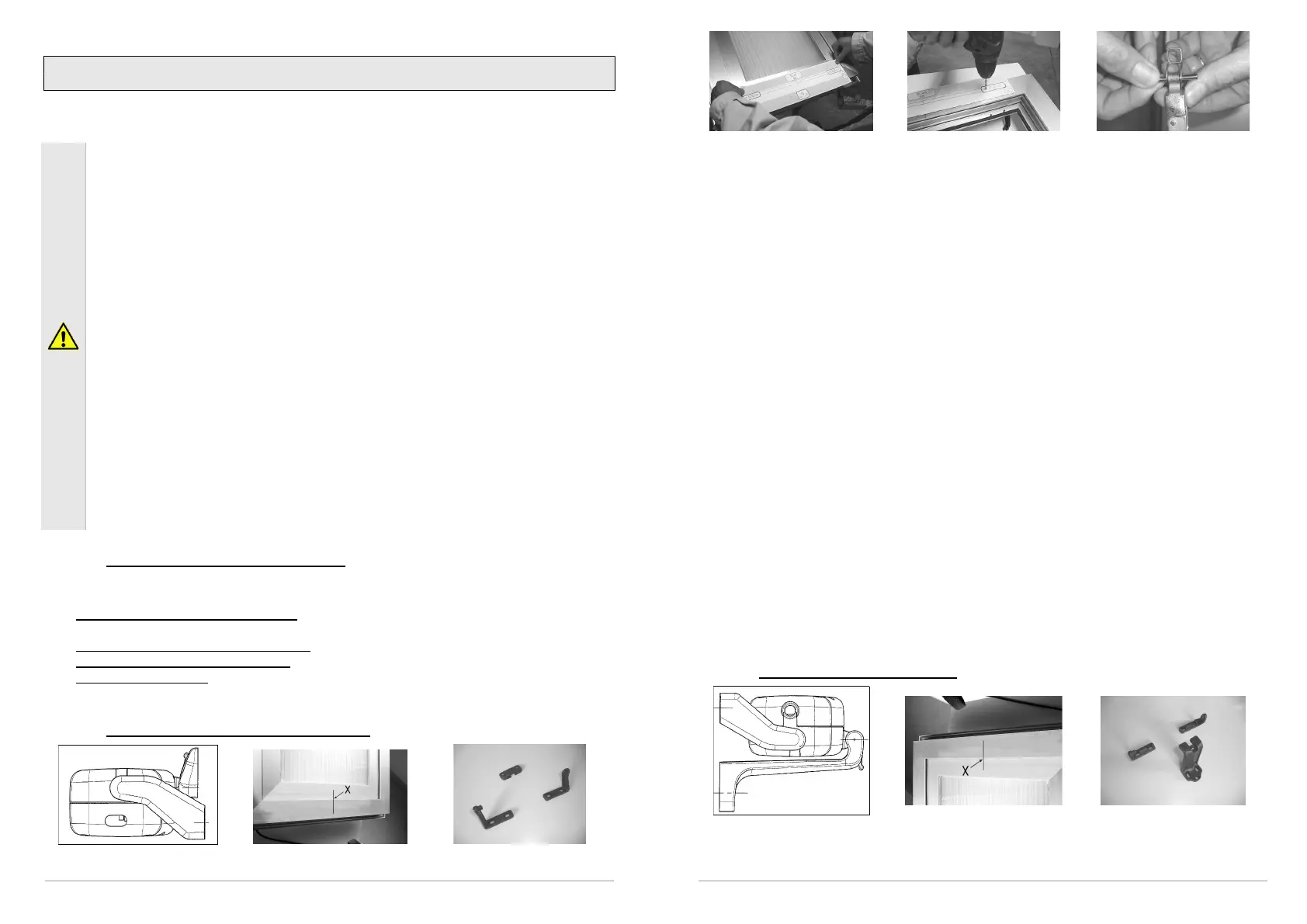
9.2. Assembly with outward opening window
Application on outward opening Figure 2 Figure 3
29
Figure 4 Figure 5 Figure 6
Above the drawing of specific application using accessories provided. For different
mountings, please contact manufacturer.
A. Pencil in an “X” over the centre line of the window frame (Fig. 2) or fairly divide it in case
of use of more Kato Syncro
3
.
B. Select the correct form of brackets (Fig. 3).
C. Attach the template to the window frame (fixed part) and line axis up with the centre line
“X” traced earlier (Fig. 4). Warning: for window frames not on the same plane, cut the
part of the template coloured in grey and fix this to the moveable part of the window
frame, taking care to keep it in the same position.
D. Bore holes in the window frame at the points indicated on the template (Fig. 5).
E. Assemble the two brackets with the distancer (to help position correctly. Once it has
served its purpose it can be removed). Mount the supports onto the frame with the
appropriate screws provided. Check that everything is aligned both horizontally and
vertically.
F. Mount the bracket for outward opening windows onto the moveable part of the frame in
accordance with the markings indicated on the template.
G. Complete assembly of the chain terminal with the rapid release hook inserted onto the pin
Ø4x32 (provided) in median position (Fig. 6).
H. Mount the actuator onto the brackets by inserting the two openings at each side onto the
corresponding pins on the brackets.
I. Rotate the actuator 90°, bring the chain terminal up to the bracket and insert the pin into
the opening on the bracket. Insert the rapid release hook into the bracket. For the first few
times, this may fairly stiff, but in time the pieces involved will adapt to their positions.
J. Check that the exit on the chain is perfectly aligned with the bracket. If the chain is not
aligned with the bracket, loosen the fixing screws and reposition the bracket correctly.
K. Check all electrical connections with the diagram on the label attached to the lead.
L. Carry out a complete check of opening and closure of the window. Once the closure
phase has been completed, check that the window frame is completely closed by
checking the pressure on the weather strips.
M. On re-entry the actuator limit switch functions automatically. The device exerts a traction
force to guarantee perfect sealing up of the weather strips.
9.3. Assembly on transom window
Application on transom window
 Loading...