32
1 2 3
F N
230V~ 50/60Hz
3
1 2
230V ~
-
+
24V
3
1
2
1 2 3
24V
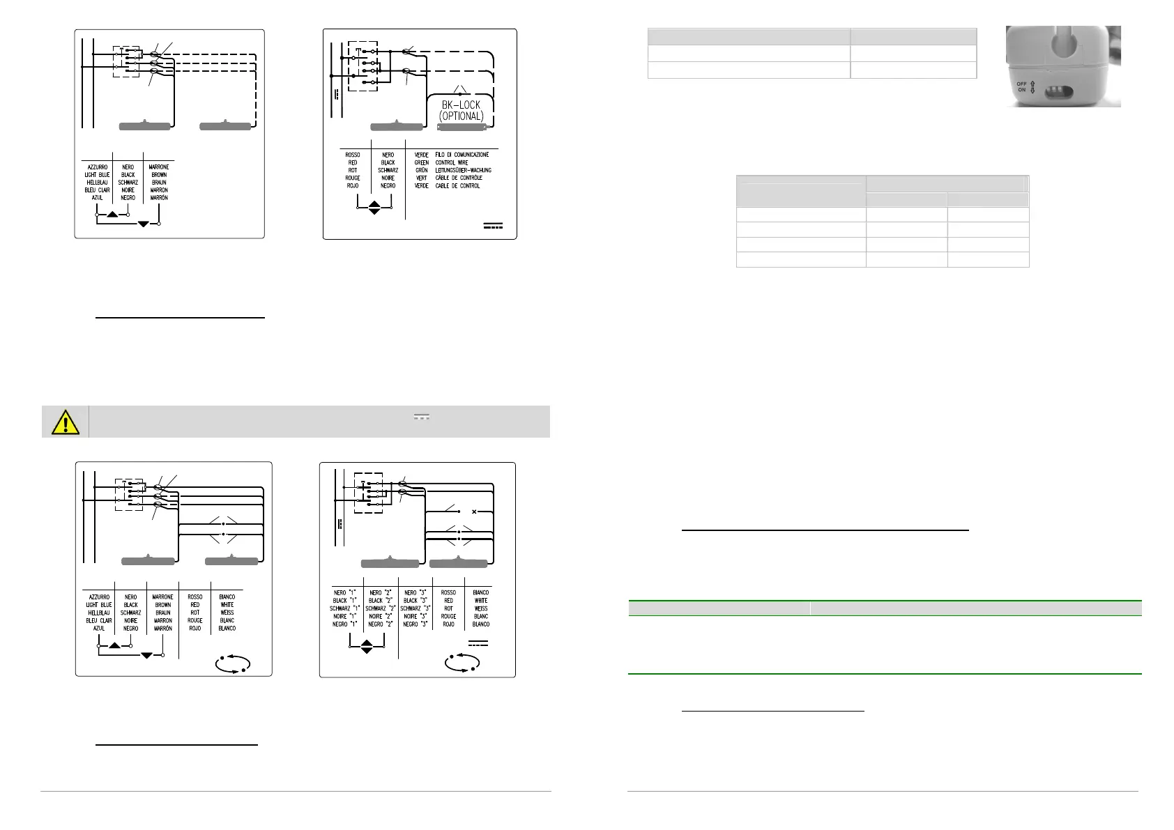
After connecting the electricity supply to the control button (bipolar with arrows if possible),
check that the up key function opens the window frame and the and down key function
closes it. In the event that keys should function to the contrary, invert cable positions.
10.2. Connections of Kato Syncro³
Cable supplied together with actuator is 2,5 m (±5%) long and it is calculated in accordance
with safety rules. See table on page 27 for conductor section indications.
Electrical connection of cables white and red has to be done with a loose connector of proper
dimensions (clamp is on equipment). Fundamental importance has a steady connection, with a
good electrical contact because passing tension is very low.
IMPORTANT FOR PRODUCT SAFETY: on actuators with 24V supply voltage, Kato
Syncro
3
version, wire Black “3”, if not used, must be insulated.
For harness, please follow these diagrams:
1 2 3 4
F N
100-230V~ 50/60Hz
3
1
4
2
110/230V ~
SYN C RO
5
5
24V
+-
2
1
1 2 3
3
54
4
5
NC
24V
SYN C R O
11. PROGRAMMING THE LIMIT SWITCHES
11.1. Programming Kato actuator
Electromechanical lock setting (only Kato 24V)
2 (two) positions can be selected, with or without electromechanical lock.
33
Mode DIP-SWITCH No. 3
With electromechanical lock ON
Without electromechanical lock OFF
Limit switches at opening
4 (four) positions can be selected for the limit switch of the outgoing chain. To program,
adjust the two dip-switches at the side of the LED. Programming is simple, immediate and
can be carried out at any time by adjusting the two dip-switches as indicated in the following
table.
Limit switches
Dip-Switch
Nr. 1 Nr. 2
110 mm OFF OFF
200 mm ON OFF
300 mm OFF ON
400 mm ON ON
After the limit switches have been programmed, run a few check manoeuvres. In the event of
error, programming can be repeated to give the desired track run.
Limit switches at closure
The limit switch at closure is automatic, electronically operated and cannot be programmed.
The actuator stops when the charge is absorbed when the window is completely closed and
the weather stripping is completely depressed. After each closure or intervention of the
electrical protection mechanism, the chain moves in the opposite direction for around 1 mm.
This is to loosen the tension of the mechanical parts and gives correct pressure to the
weather stripping.
When the window frame is closed, check that the chain terminal is at least a couple of
millimetres away from the actuator body.
This ensures proper closure for the window and ensures all weather stripping is sealed. If the
chain terminal is not positioned correctly there is no guarantee that the window will close
completely. Check that attachments and support brackets are firmly fixed to the window
frame and that all screws have been correctly tightened.
11.2. Luminous indications on led (only for Kato 230V)
Before activating the actuator, familiarise yourself with messages indicated by the red led
opposite the lead. This will allow you to check that the machine is functioning properly or
allow you to recognize possible irregularities. The LED is only visible when the actuator has
been turned on.
Constantly lit Motor in use.
Off and flashing Motor has regularly reached a limit stop but is still
connected to electricity supply.
Normal regular blinking Motor in electronic protection due to excessive charge
11.3. Programming the Kato Syncro³
The actuators leave the factory programmed and synchronized in pairs, thus the user only
needs to select the desired stroke. It is recommended that you check to ensure that all the
chains are in the same position and the actuators are connected properly as per paragraph
10.2. In the event the settings are lost, a new synchronization must be performed according
to the procedures described below.