30
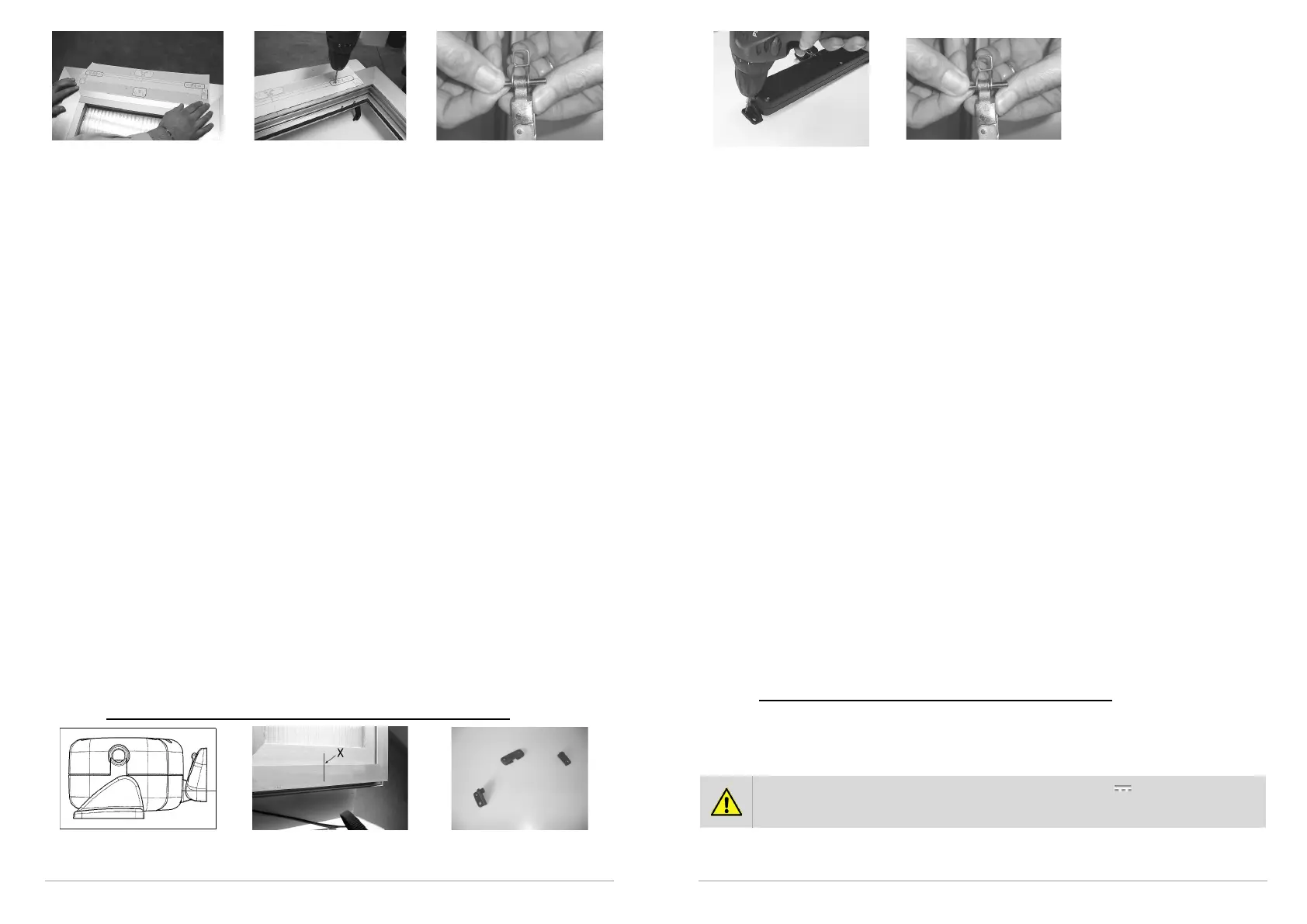
Figure 9 Figure 10 Figure 11
Above the drawing of specific application using accessories provided. For different
mountings, please contact manufacturer.
A. Before starting, check that there are at least two mechanical compass safety stops
or other form of stops connected to the frame, and ensure that the stops can
prevent any accidental fall of the window. Your safety is at hand.
B. Pencil in an “X” over the centre line of the window frame (Fig. 7) or fairly divide it in case
of use of more Kato Syncro
3
.
C. Select the correct form of brackets (Fig. 8).
D. Attach the template to the window frame (fixed part) and line axis up with the centre line
“X” traced earlier (Fig. 9). Warning: for window frames not on the same plane, cut the
part of the template coloured in grey and fix this to the moveable part of the window
frame, taking care to keep it in the same position.
E. Bore holes in the window frame at the points indicated on the template (Fig. 10).
F. Assemble the two brackets with the distancer (to help position correctly. Once it has
served its purpose it can be removed). Mount the supports onto the frame with the
appropriate screws provided. Check that everything is aligned both horizontally and
vertically.
G. Mount the bracket for outward opening windows onto the moveable part of the frame in
accordance with the markings indicated on the template.
H. Complete assembly of the chain terminal with the rapid release hook inserted onto the
provided pin Ø4x32 in median position (Fig. 11).
I. Mount the actuator onto the brackets by inserting the two openings at each side onto the
corresponding pins on the brackets.
J. Rotate the actuator 90°, bring the chain terminal up to the bracket and insert the pin into
the opening on the bracket. Insert the rapid release hook into the bracket.
K. Check that the exit on the chain is perfectly aligned with the bracket. If the chain is not
aligned with the bracket, loosen the fixing screws and reposition the bracket correctly.
L. Check all electrical connections with the diagram on the label attached to the lead.
M. Carry out a complete check of opening and closure of the window. Once the closure
phase has been completed, check that the window frame is completely closed by
checking the pressure on the weather strips.
N. On re-entry the actuator limit switch functions automatically. The device exerts a traction
force to guarantee perfect sealing up of the weather strips.
9.4. Vertical assembly of the actuator on outward opening window
Vertical application on outward
opening
Figure 12 Figure 13
31
Figure 14 Figure 15
Above the drawing of specific application using accessories provided. For different
mountings, please contact manufacturer.
A. Pencil in an “X” over the centre line of the window frame (Fig. 12) or fairly divide it in case
of use of more Kato Syncro³.
B. Select the correct form of brackets (Fig. 13).
C. Fold the template along the green dotted line and keep in position at 90°. Attach one part
to the window frame (fixed part), taking care to line up the axis with the “X” previously
pencilled in on the central line and line the folded part up against the moveable part of the
frame. Warning: as various different applications are possible, place the actuator in a
central position and adjust the positions of the brackets, taking care to keep the actuator
aligned with the window section.
D. Bore holes into the window frame at the points indicated (Fig. 14).
E. Mount the bracket for outward opening windows onto the moveable part of the frame in
accordance with the markings indicated on the template.
F. Complete assembly of the chain terminal with the rapid release hook inserted onto the
provided pin Ø4x32 in median position (Fig. 15).
G. Mount the two brackets on to the sides of the actuator.
H. Position the actuator onto the window frame and line up with the holes bored earlier. Fix
the actuator in position with the screws provided.
I. Bring the chain terminal up to the bracket and insert the pin into the hole on the bracket.
Attach the rapid release hook to the bracket.
J. Check that the exit of the chain is perfectly aligned with the bracket. If the chain is not
aligned, loosen the fixing screws and reposition the bracket correctly.
K. Check all electrical connections with the diagram on the label attached to the lead.
L. Carry out a complete check of opening and closure of the window. Once the closure
phase has been completed, check that the window frame is completely closed by
checking the pressure on the weather strips.
M. On re-entry the actuator limit switch functions automatically. The device exerts a traction
force to guarantee perfect sealing up of the weather strips.
10. ELECTRICAL CONNECTIONS
10.1. Connections of Kato (+ optional BK-Lock electro lock)
The actuator comes with a 2 m long circa (±5%) lead which has been calculated in
accordance with safety rules. In the event that the distance between the actuator and the
control button should exceed this length, the cable should be extended. See table on page
27 for conductor section indications.
IMPORTANT FOR PRODUCT SAFETY: on actuators with 24V supply voltage, Kato
version, the Green wire "3", if not used with BK-LOCK electro lock, must be
insulated.
For harness, please follow the following diagrams.
 Loading...