26
The actuator is manufactured in accordance with the Directives and following
Regulations listed in the attached Declaration of Incorporation and Conformity .
Electrical connections must conform to regulations in force for the design and set up
of electrical equipment.
To ensure efficient separation from the grid, an approved type of bipolar “dead-man”
switch should be used. An omnipolar general power switch with minimum distance of
3 mm between contacts should be installed upstream of the control line.
The KATO actuator is packed in one single carton. Each package contains:
Actuator with 2 metres (±5%) lead, 2,5 metres for Kato Syncro
3
.
Standard support brackets with distancer (A).
Bracket for vertical assembly of the actuator (B).
Bracket for transom window (C).
Bracket for outward opening fixture (D).
Template for boring.
Small parts packaging.
Instruction manual.
IMPORTANT. The Syncro³ version of the actuator is packed in a cardboard box with
two units and all accessories needed and is shipped already tested. However, the
RESET procedure must still be performed.
When installing a system that requires the use of several Syncro³ actuators or a BK-
LOCK electro-lock, a new RESET procedure must be performed.
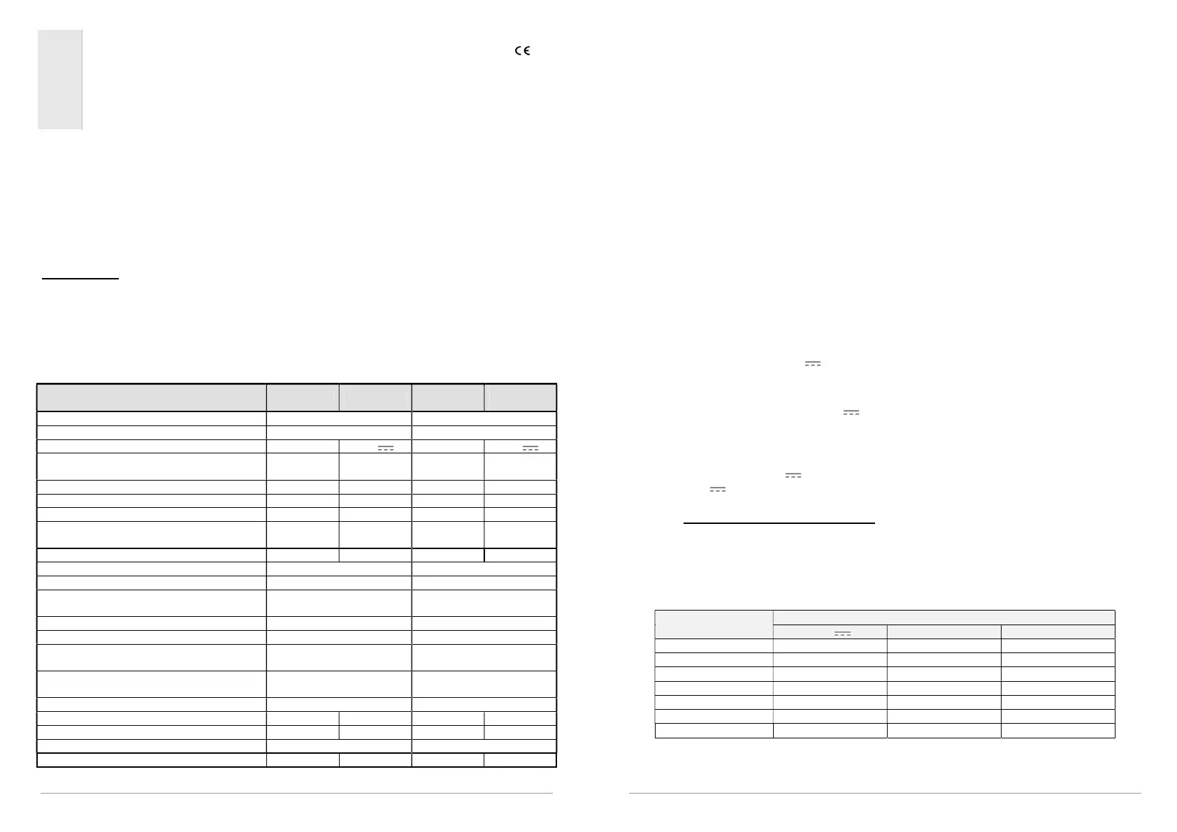
6. TECHNICAL DATA
Model KATO 230V
KATO 24V
SYNCRO
230V
SYNCRO
24V
Force exerted by thrust and traction (F
) 300N 300N
Strokes (S
) 110/ 200/ 300/ 400 mm 100/ 200/ 400 mm
Power supply voltage (U
) 230V~ 24V 110-230V~ 24V
Rated absorbed current (I
N
)
0,25 A 0,9 A 0,34A-
0,21A
0,95 A
Power absorbed at nominal load (P
) ~27 W ~22 W ~26-27 W ~23 W
No load speed 14,6 mm/s 14,6 mm/s 8,9 mm/s 8,9 mm/s
Duration of no load stroke (400 mm) 27 s 27 s 44 s 44 s
Electrical insulation
Class II Class III
(Selv)
Class II Class III
(Selv)
Type of service (D
) 2 cycles 5 cycles 2 cycles 5 cycles
Operating temperature - 5 + 65 °C - 5 + 65 °C
Protection index for electrical devices IP30 IP30
Adjustment of connection to window frame
Automatic definition of
position
Automatic definition of
position
Parallel powering of two or more motors Yes (max 20) Yes (max 10)
Synchronised function No Yes (max 8)
Holding nominal force (it can vary
according to the chosen brackets)
1600 N 1600 N
Stroke-end at opening
Electronic with regulation
by means of dip-switches
Electronic with regulation
by means of dip-switches
Stroke-end at closing At absorption of power At absorption of power
Signalling ‘window open/window closed’ No No No No
Length of power cable 2 m 2 m 2,5 m 2,5 m
Dimensions 386,5x59x37 mm 386,5x59x37 mm
Weight (Kg) 0,980 0,970 1,150 1,150
Any information reported in this table is not binding and may be susceptible to variations without notice.
27
7. ID PLATE AND MARKING DATA
The KATO and KATO SYNCRO³ actuators have CE marking and comply with the Standards
listed in the Declaration of Conformity. They also come with a Declaration of Incorporation,
due to their classification by the Machinery Directive as “partly completed machines”. Both
declarations are included in the final pages of this manual.
The plate data is displayed on an adhesive label placed on the outside of the casing, which
must remain intact and visible.
The main information it displays includes: manufacturer's address, product name - model
number, technical characteristics, production date and serial number.
In the event of a complaint, please indicate the serial number (SN) displayed on the label.
An explanation of the symbols used on the label to abbreviate the technical characteristics is
given in the table in the chapter on “TECHNICAL DATA”.
8. ELECTRICAL POWER SUPPLY
The KATO and KATO SYNCRO³ actuators are commercially available in four versions:
1. KATO 230V: runs on grid tension of 230V~ 50/60Hz, with a three wire cable (LIGHT
BLUE, common neutral; BLACK, phase open; BROWN, phase closed).
2. KATO SYNCRO
3
230V: runs on grid tension of 110-230V~ 50/60Hz, with a five wire cable
(LIGHT BLUE, common neutral; BLACK, phase open; BROWN, phase closed). The
additional wiring (RED and WHITE) is for electronic synchronisation (NEKOS Patent).
3. KATO 24V: runs on 24V , with three wire cable, (RED “1”, connected to the +
(positive) closes; BLACK “2”, connected to the + (positive) opens. A third wire GREEN
“3”, is used for the possible connection to the BK-Lock electromechanical lock).
4. KATO SYNCRO
3
24V: runs on 24V , with five wire cable, (BLACK “1”, connected to the
+ (positive) closes; BLACK “2”, connected to the + (positive) opens. The third wire
BLACK “3”, is used for the possible connection to the BK-Lock electromechanical lock).
The additional wiring (RED and WHITE) is for electronic synchronisation (NEKOS Patent).
Low tension actuators 24V must be powered using a security feeder with an output
tension of 24V (min. 20.4V, max. 28.8V).
8.1. Selection of power cable section
Tension falls due to current passage in conductors is a basic aspect for safety and good
appliance function. It is therefore extremely important that the conductor section in function of
cable length is calculated correctly.
The following table indicates cable lengths for an actuator connected at nominal charge.
CABLE SECTION
0.50 mmq ~20 m ~300 m ~1400 m
0.75 mmq ~30 m ~450 m ~2100 m
1.00 mmq ~40 m ~600 m ~2800 m
1.50 mmq ~60 m ~900 m ~4000 m
2.50 mmq ~100 m ~1500 m ~6800 m
4.00 mmq ~160 m ~2500 m ~11000 m
6.00 mmq ~240m ~3700 m ~15000 m

 Loading...