NS20A & NS20N Heavy Duty Gun Page 5 Revision 1.20 2/19/08
LIFT AND LIFT ADJUSTMENTS
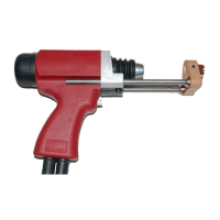
Series 3000 (NS-20A HD)
1. Load stud and ferrule into gun with proper
plunge setting for welding.
2. Set weld time at approximately ½ second. If
control unit is equipped with a Weld Monitor
Module, set 3-position switch in the "Lift
Check" position.
3. Place gun in normal welding position on a
piece of wood or other insulated type surface.
4. Depress trigger button as if to weld.
5. Measure the inward movement of the shaft
extension. This is the actual lift under the
welding condition.
Note: Triggering the gun in the air away from the
work surface will cause the gun to lift. The lift in
open air will be greater than when the gun is in the
actual or simulated weld condition.
Caution: Erratic lift can be caused by low voltage;
therefore, it is suggested that a minimum of 65
volts open circuit voltage be used when checking
lift or operating the stud welding equipment.
To Change Lift:
Remove rear cap on gun, loosen lock screw and
position the adjustable core as required (See Figure
3).
To Increase Lift, screw out (counter-clockwise)
the adjustable core.
To Decrease Lift, screw in (clockwise) the
adjustable core.
After proper lift is obtained, lock adjustable core in
position by tightening lock screw. Replace rear cap
on gun. Adjust for proper weld time.
Recommended Lift Settings for Steel Studs
For welding:
½” diameter studs or less.................................1/16”
⅝” and ¾” diameter studs ...............................3/32”
⅞” diameter studs and over .................7/64” to 1/8”