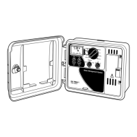
INSTALLATION INSTRUCTIONS
For models
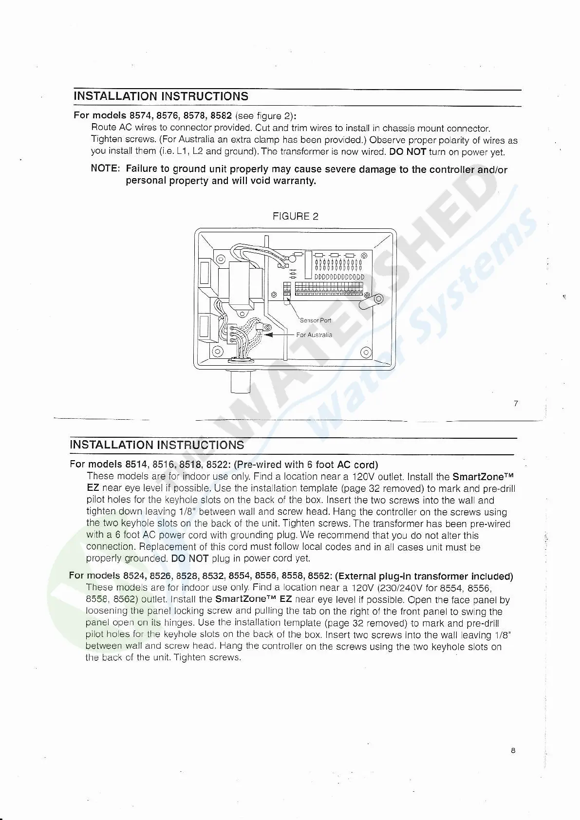
8574, 8576, 8578, 8582
(see
iigure
2):
Rolte
AC wires to connector
provided.
Cut and trjrn wtres to install
in chassis mount connectoT,
Tighten
screws.
(For
Austra|a
an extra clamp has
been
provided.)
Observe
proper
polarity
of wires as
you
installthem
(i.e.
11, L2
and
ground).
The transiormer
is now wired. OO NOT turn
on
power yet.
NOTE:
Failure to
grouncl
unit
properly
may cause severe
damage to the controlter
and/or
personal
property
and will void warranty.
F]GURE
2
INSTALLATION
INSTRUCTIONS
For models
8514j 8516,8518,8522:
(Pre-wired
with 6 foot AC
cord)
These mode
s are lor indoor use on
y.
Find
a
location near
a 120V ouilet. lnstall the
SmartzonerM
EZ near
eye levei if
possib
e. Use
the insta latron template
(page
32 removed) to mark
and
pre-drill
pilot
holes
for the keyho
e s ots on
the
back
oi the box. lnse(
the two screws into the watt
and
tighten
down leaving 1/8"
between
wall
and
screw head. Hang
the coniro ler
on the screws ustng
the two
keyhole slots
on the back of the
unit. T
ghten
screws. The transforrner has
been
pre-wired
wth
a 6 loot AC
power
cord wiih
grounding
plug.
We recommend
that
yo!
do
not
a ter thrs
connectron. Replacement
oi this cord
mustfolow local
codesandinal
casesuniimustbe
properly
groLrnded.
DO NOT
p[]g
in
power
cord
yei.
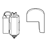
For models
8524,8526, 8528,8532,8554,8556,8558, 8562:
(External plug-in
transformer
included)
These
mode s are lor indoor use only.
F nd
a
locatron
near
a 120V
(230/240V
ior
8554, 8556,
8558, 8562) outlel. lnstall the SmartzonerM
EZ
near
eye level if
possible.
Open the face
panel
by
loosening
the
panel
lock ng screw
and
pu
ling
the tab
on the right oi the front
pane
to swing the
pane
open on its hinges. Use
the insiallation
template (page
32 removecl),to mark and
pre-driil
pllot
holes ior
the keyhole
slols on the back
of the
box. lnsert
two screws ifto the wall leaving 1/8
between
wall and screw head. Hang
the controller
on the screws
using lhe two keyho e slots on
the back of
the un t. Tjghten screws.
 Loading...