T E C H L I N E A S ™ D E S I G N G U I D E
NETAFIM @BCL@C40BDC65.doc 21/12/2009 17
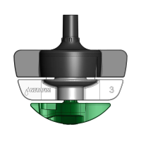
AIR/VACUUM RELIEF VALVES:
Air/Vacuum relief valve freely allows air into a zone after shut down. It also ensures a vacuum
within non Anti Siphon dripperline system doesn’t suck debris or dirt back in to the dripperline. It
also provides a means of releasing air from the dripperline when the zone is turned on,
eliminating air pockets and speeding up the dripperline operation.
Install Air/Vacuum Relief Valve at the highest point in the drip system.
Install one Air/Vacuum Relief Valve for every 40L/M of zone flow.
Ensure that all of the rows of Dripperline can take advantage of the Air/Vacuum Relief
Valve; install it/them along a lateral that runs perpendicular to the dripperline laterals.
This may be a collecting manifold, or a special lateral connecting all rows of dripperline,
such as going over a mound.
All Air/Vacuum Relief Valves should be installed in a valve box with a gravel sump. This
will ensure that the only clean air will enter the drip system.
Note: Larger Air Release valves are available for large projects.