1. Use the animation or the step-by step instructions to complete the cabling between the controllers and to
the switches:
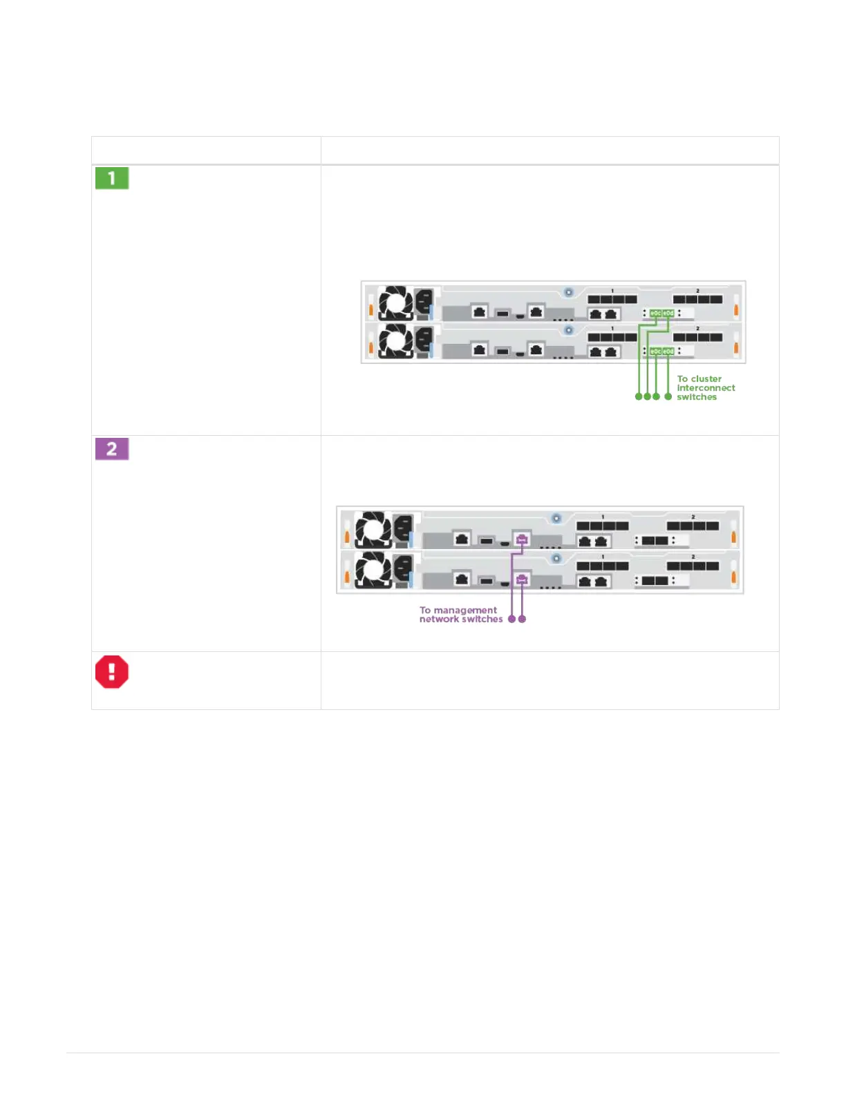
Cabling a switched cluster
Step Perform on each controller
Cable the cluster interconnect ports to the 25 GbE cluster
interconnect switches.
• e0c
•
e0d
Cable the wrench ports to the management network switches with the
RJ45 cables.
DO NOT plug in the power cords at this point.
2. To complete setting up your system, see Step4: Completing system setup and configuration.
Optional cabling: Cable configuration-dependent options
You have configuration-dependent optional cabling to the Fibre Channel or iSCSI host
networks or direct-attached storage. This cabling is not exclusive; you can have cabling
to a host network and storage.
Option 1: Cable to a Fibre Channel host network
Fibre Channel ports on the controllers are connected to Fibre Channel host network
switches.
Contact your network administrator for information about connecting the system to the switches.
1098
 Loading...