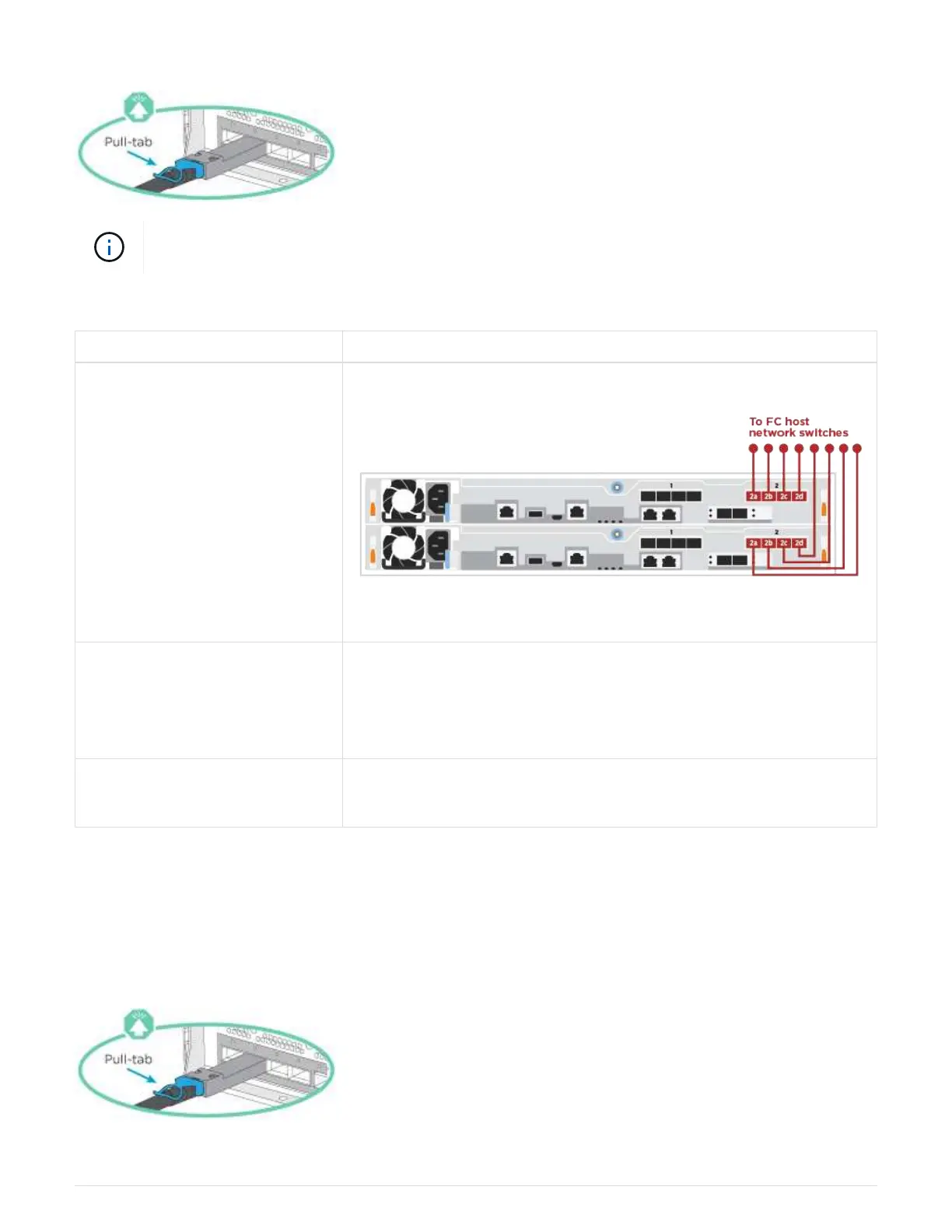
Be sure to check the illustration arrow for the proper cable connector pull-tab orientation.
As you insert the connector, you should feel it click into place; if you do not feel it click, remove
it, turn it around and try again.
+
Step Perform on each controller module
1 Cable ports 2a through 2d to the FC host switches.
2 To perform other optional cabling, choose from:
•
Option 2: Cable to a 25GbE data or host network
• Option 3: Cable the controllers to a single drive shelf
3 To complete setting up your system, see Step4: Completing system
setup and configuration
.
Option 2: Cable to a 25GbE data or host network
25GbE ports on the controllers are connected to 25GbE data or host network switches.
Contact your network administrator for information about connecting the system to the switches.
Be sure to check the illustration arrow for the proper cable connector pull-tab orientation.
1099
 Loading...