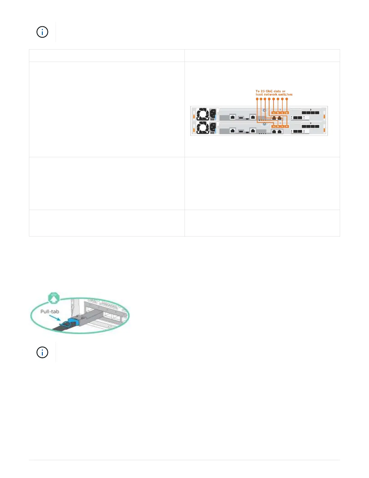
As you insert the connector, you should feel it click into place; if you do not feel it click, remove
it, turn it around and try again.
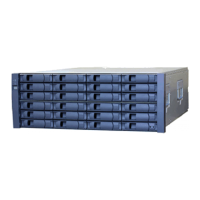
Step Perform on each controller module
1 Cable ports e4a through e4d to the 10GbE host
network switches.
2 To perform other optional cabling, choose from:
•
Option 1: Cable to a Fibre Channel host network
• Option 3: Cable the controllers to a single drive
shelf
3 To complete setting up your system, see Step4:
Completing system setup and configuration
.
Option 3: Cable the controllers to a single drive shelf
You must cable each controller to the NSM modules on the NS224 drive shelf.
Be sure to check the illustration arrow for the proper cable connector pull-tab orientation.
As you insert the connector, you should feel it click into place; if you do not feel it click, remove
it, turn it around and try again.
1. Use the animation or the step-by-step instructions to cable your controller modules to a single shelf.
Cabling the controllers to a single NS224
1100
 Loading...