EasyManua.ls Logo

NetApp FAS22 Series User Manual

NetApp FAS22 Series
9 pages
To Next Page IconTo Next Page
Page #1 background imageLoading...
Page #1 background image
Replacing the chassis on a FAS22xx system
To replace the chassis, you must remove the power supplies, hard drives, and controller module or modules from the old
chassis, remove the old chassis from the equipment rack or system cabinet, install the new chassis, and then reinstall the
components into the new chassis.
Before you begin
All other components in the system must be functioning properly; if not, you must contact technical support.
About this task
You can use this procedure with all versions of Data ONTAP supported by your system.
In this procedure, a
Cluster-Mode system
refers to a system running Data ONTAP 8.x in Cluster-Mode. A
7-Mode system
refers to a system running Data ONTAP 8.x in 7-Mode.
This procedure refers to
HA pairs
, which in releases prior to Data ONTAP 8.0 were called
active/active configurations
.
This procedure assumes you are moving all disk drives to the new chassis.
This procedure is written with the assumption that the chassis is nonfunctional and, therefore, the controller modules in it are
not serving data.
This procedure is written with the assumption that you are moving the controller module or modules to the new chassis, and
that the chassis is a new component from NetApp.
Steps
1.
Removing the power supplies
on page 1
2.
Removing the controller module
on page 2
3.
Moving disk drives to the new chassis
on page 3
4.
Removing the chassis from the equipment rack or system cabinet
on page 5
5.
Installing the new chassis into the equipment rack or system cabinet
on page 5
6.
Installing the power supplies
on page 5
7.
Reinstalling the controller modules and booting the system
on page 6
8.
Verifying and setting the HA state of the chassis
on page 6
9.
Running diagnostics on the chassis
on page 7
10.
Completing the replacement process
on page 9
Removing the power supplies
To remove the power supplies from the chassis, you must perform a specific sequence of steps.
Steps
1.
If you are not already grounded, properly ground yourself.
2.
If you have not already done so, turn off the power to the target power supply and remove the power cord.
3.
Squeeze the latch on the cam handle until it releases, then open the cam handle fully to release the power supply from the
midplane.
1
215-06298_A0 Copyright
©
2012 NetApp, Inc. All rights reserved.
Question and Answer IconNeed help?

Do you have a question about the NetApp FAS22 Series and is the answer not in the manual?

NetApp FAS22 Series Specifications

General IconGeneral
ModelFAS2220, FAS2240, FAS2252
Maximum Raw Capacity (FAS2220)144 TB
Drive Types SupportedSAS, SATA, SSD
Form Factor (FAS2252)4U
Controller TypeDual Controller
Storage TypeHybrid (SSD and HDD)
Supported ProtocolsNFS, CIFS, iSCSI, FC
Maximum Number of Drives24
RAID SupportRAID4, RAID-DP
Form Factor2U
Power SupplyRedundant
Management InterfaceNetApp OnCommand System Manager, CLI
Network Ports10 GbE, 1 GbE
Operating SystemNetApp Data ONTAP
Processor (FAS2220)Dual-core Intel Xeon
Processor (FAS2240, FAS2252)Quad-core Intel Xeon

Summary

Removing the power supplies

Preparing and Releasing Power Supply

Ground yourself, turn off power, remove cord, and release PSU from midplane.

Extracting Power Supply

Slide the power supply out of the system, supporting its weight, and repeat for remaining supplies.

Removing the controller module

Disconnecting and Preparing Module

Ground yourself, unplug cables/SFPs, and remove cable management arms.

Releasing and Extracting Controller Module

Release the module using the cam handle and pull it out of the chassis.

Moving disk drives to the new chassis

Removing Disk Drives

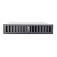
Remove bezel, press release button, and slide drives out of the chassis.

Installing Disk Drives

Align drives in new chassis, push them in, and lock the cam handles securely.

Transferring Operator Display Panel

For FAS2240-2, remove the operator display panel and install it in the new chassis.

Removing the chassis from the equipment rack or system cabinet

Installing the new chassis into the equipment rack or system cabinet

Installing the power supplies

Reinstalling the controller modules and booting the system

Seating Controller Modules

Insert controller modules, seat cam handles, and reinstall cable management arms.

Connecting Power and Booting System

Connect power supplies, turn them on, and boot to Maintenance mode.

Verifying and setting the HA state of the chassis

Displaying HA Configuration

Display the HA state of the local controller module and chassis using the ha-config show command.

Modifying HA Configuration

Update the HA state if it does not match the system configuration using the ha-config modify chassis command.

Exiting Maintenance Mode

Exit Maintenance mode by entering the halt command to reach the LOADER prompt.

Running diagnostics on the chassis

Initiating System-Level Diagnostics

Enter boot_diags at LOADER prompt and sldiag at Maintenance prompt.

Executing Diagnostic Tests

Clear logs, run environmental tests, and view status using sldiag commands.

Analyzing Diagnostic Results

Verify hardware status, proceed based on test completion or failures, and rerun if necessary.

Completing the replacement process

Related product manuals