© NETGEAR, Inc., NETGEAR and the NETGEAR Logo
are trademarks of NETGEAR, Inc. Any non‑NETGEAR
trademarks are used for reference purposes only.
Support
Thank you for purchasing this NETGEAR product. You can visit
https://www.netgear.com/support/ to register your product, get help, access the
latest downloads and user manuals, and join our community. We recommend
that you use only ofcial NETGEAR support resources.
Si ce produit est vendu au Canada, vous pouvez accéder à ce document en
français canadien à https://www.netgear.com/support/download/.
(If this product is sold in Canada, you can access this document in Canadian
French at https://www.netgear.com/support/download/.)
For regulatory compliance information including the EU Declaration of
Conformity, visit https://www.netgear.com/about/regulatory/.
See the regulatory compliance document before connecting the power supply.
Do not use this device outdoors. If you connect cables or devices that are
outdoors to this device, see https://kb.netgear.com/000057103 for safety and
warranty information.
Specications
Specication Description
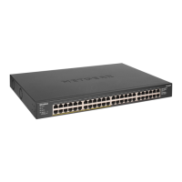
Network interfaces 48 Gigabit Ethernet RJ-45 ports that support 1G, 100 M, and 10M
24 PoE/PoE+ ports
Power input 100-240VAC, 8A max
Max PoE budget 380W
Dimensions
(W x D x H)
17.3 x 12.2 x 1.7 in. (440 x 310 x 43 mm)
Weight 10.1 lb (4.56 kg)
Operating temperature 32–113°F (0–45°C)
Operating humidity 10%–90% relative humidity, noncondensing
Compliance FCC class A, CB, CE class A, VCCI class A, RCM class A, KC, BSMI
PoE considerations
The PoE and PoE+ power supplied by the switch is prioritized in ascending port
order: Ports 1–24 support PoE and PoE+ with a total power budget of 380W.
If the power requirements for the attached powered devices (PDs) exceed
the total power budget of the switch, the PD on the highest-numbered port
is disabled to make sure that the PDs connected to the higher-priority, lower-
numbered ports are supported rst.
A PD listed as an 802.3at PoE powered device does not necessarily require
the maximum power limit of the specication. Many PDs require less power,
potentially allowing more PoE ports to be active simultaneously.
The following table shows the standard power ranges calculated with the
maximum cable length of 328 feet (100 meters).
Device
Class
Standard Class Description Power
Reserved by
the Device
Power
Delivered to
the Device
0 PoE and PoE+ Default power (full) 0.44W 0.44W–12.95W
1 PoE and PoE+ Very low power 4.0W 0.44W–3.84W
2 PoE and PoE+ Low power 7.0W 3.84W–6.49W
3 PoE and PoE+ Mid power 15.4W 6.49W–12.95W
4 PoE+ only High power 30.0W 12.95W–25.5W
If a device receives insufcient PoE power from the switch, consider using a
shorter cable.
PoE Troubleshooting
Here are some tips for correcting PoE problems that might occur:
• If the PoE Max LED is solid yellow, disconnect one or more PoE devices to
prevent PoE oversubscription.
• For each powered device (PD) that is connected to the switch, the associated
PoE LED on the switch lights solid green. If the PoE LED lights solid yellow, a
PoE fault occurred and PoE halted because of one of the conditions listed in
the following table.
PoE Fault Condition Possible Solution
A PoE-related short circuit occurred on the port. The problem is most likely with
the attached PD. Check the
condition of the PD, or restart
the PD by disconnecting and
reconnecting the PD.
The PoE power demand of the PD exceeded
the maximum level that the switch permits. The
maximum level is 15.4 for a PoE connection or
30W for a PoE+ connection
The PoE current on the port exceeded the
classication limit of the PD.
The PoE voltage of the port is outside the range
that the switch permits
Restart the switch to see if the
condition resolves itself.
Mount the switch in a rack
We recommend that you use the brackets and screws that came with the switch.
1. Attach the mounting brackets to the side of the switch.
2. Insert the screws through each bracket and into the bracket mounting holes
in the switch.
3. Tighten the screws with a No. 1 Phillips screwdriver to secure each bracket.
4. Align the mounting holes in the brackets with the holes in the rack, and insert
two pan-head screws with nylon washers through each bracket and into the
rack.
5. Tighten the screws with a No. 2 Phillips screwdriver to secure mounting
brackets to the rack.
October 2019
 Loading...