Page 1 of 21
@2005 NETGEAR, Inc. NETGEAR, the Netgear logo, Auto Uplink, ProSafe and Everybody’s connecting are trademarks or registered trademarks
of Netgear, Inc. in the United States and/or other countries. Other brand and product names are trademarks of their respective holders. Information
is subject to change without notice. All rights reserved.
Statement of Conditions
In the interest of improving internal design, operational function, and/or reliability, NETGEAR reserves the right to make changes to the products
described in this document without notice. NETGEAR does not assume any liability that may occur due to the use or application of the product(s) or
circuit layout(s) described herein.
Certificate of the Manufacturer/Importer
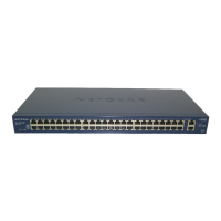
It is hereby certified that the NETGEAR ProSafe 48 port 10/100 Smart Switch with 2 Gigabit ports FS750T2 has been suppressed in accordance
with the conditions set out in the BMPT-AmtsblVfg 243/1991 and Vfg 46/1992.The operation of some equipment (for example, test transmitters) in
accordance with the regulations may, however, be subject to certain restrictions. Please refer to the notes in the operating instructions.
Federal Office for Telecommunications Approvals has been notified of the placing of this equipment on the market and has been granted the right
to test the series for compliance with the regulations.
Voluntary Control Council for Interference (VCCI) Statement
This equipment is in the first category (information equipment to be used in commercial and/or industrial areas) and conforms to the standards set
by the Voluntary Control Council for Interference by Data Processing Equipment and Electronic Office Machines that are aimed at preventing radio
interference in commercial and/or industrial areas.
Consequently, when this equipment is used in a residential area or in an adjacent area thereto, radio interference may be caused to equipment
such as radios and TV receivers.
Federal Communications Commission (FCC) Compliance Notice: Radio Frequency Notice
This device complies with part 15 of the FCC Rules. Operation is subject to the following two conditions:
This device may not cause harmful interference.
This device must accept any interference received, including interference that may cause undesired operation.
Note: This equipment has been tested and found to comply with the limits for a Class A digital device, pursuant to part 15 of the FCC Rules. These
limits are designed to provide reasonable protection against harmful interference in a residential installation. This equipment generates, uses, and
can radiate radio frequency energy and, if not installed and used in accordance with the instructions, may cause harmful interference to radio
communications. However, there is no guarantee that interference will not occur in a particular installation. If this equipment does cause harmful
interference to radio or television reception, which can be determined by turning the equipment off and on, the user is encouraged to try to correct
the interference by one or more of the following measures:
Reorient or relocate the receiving antenna.
Increase the separation between the equipment and receiver.
Connect the equipment into an outlet on a circuit different from that which the receiver is connected.
Consult the dealer or an experienced radio/TV technician for help.
EN 55 022 Declaration of Conformance
This is to certify that the NETGEAR ProSafe 48 port 10/100 Smart Switch with 2 Gigabit ports FS750T2 is shielded against the generation of radio
interference in accordance with the application of Council Directive 89/336/EEC, Article 4a. Conformity is declared by the application of EN 55024
Class A (CISPR 22).
EN 55 022 and EN 55 024 Statements
This is to certify that the NETGEAR ProSafe 48 port 10/100 Smart Switch with 2 Gigabit ports FS750T2 is shielded against the generation of radio
interference in accordance with the application of Council Directive 89/336/EEC, Article 4a. Conformity is declared by the application of EN 55 022
Class A (CISPR 22) and EN 55 024.
Warning: This is a Class A product. In a domestic environment, this product may cause radio
interference, in which case the user may be required to take appropriate measures.


 Loading...