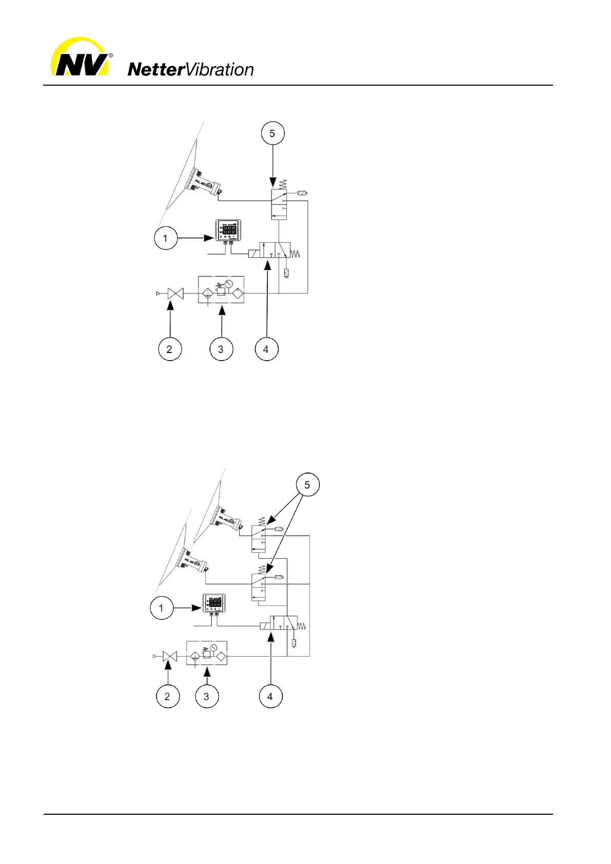
Actuating valve on customer's site
3/2-way valve (pneumatic)
The main air is always at the
3/2-way valve (5) max. 1 m
away from the PKL. The control
line from the actuating valve (4)
on the customer's site to the
PKL may be longer (e.g. 50 m).
For longer supply and control
lines, the charging time of the
PKL is several seconds. For
long air lines, set a pause and
duty time on the Electronic Tim-
er AP (1) to a minimum of at
least 5 s. If shorter lines are
used, reduce these times ac-
cordingly, e.g. to 2-3 s.
Actuating valve on customer's site
3/2-way valve (pneumatic)
It is possible to operate several
PKL in parallel with just one con-
trol and an actuating valve (4).
The connection lines from the
3/2-way valve (5) to the PKL must
be max. 1 m long, otherwise the
membrane in the PKL moves too
slowly and does not reach the
end position.
If required, install the actuating
valve (4) at a larger distance if
additional 3/2-way valves (5) are
used.
If several PKL are in operation,
the supply line must not be longer
than 50 m.
Installation
with long
supply line
all types of
PKL except
740
Installation
of several PKL
 Loading...