Do you have a question about the NEUTRIK powerCON and is the answer not in the manual?
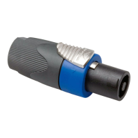
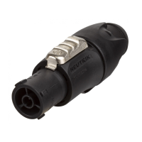
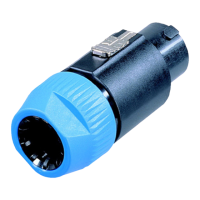
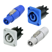
Mating connectors are identified by mechanical keyways and color for proper pairing.
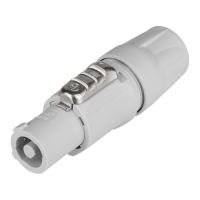
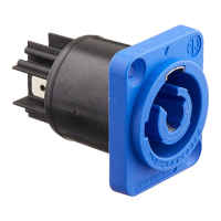
Distinguishes A type (blue, POWER IN) and B type (gray, POWER OUT) connectors.
Place the bushing and chuck over the cable, noting chuck size compatibility.
Prepare the cable with specified outer diameter and wire size for assembly.
Insert wires into terminals and fasten with POZIDRIV #1, torque 0.5 Nm.
Slide the insert and chuck into the housing, aligning the chuck nose and keyway.
Fasten the bushing using a fork wrench (SW 22) with a minimum torque of 2.5 Nm.
| Current Rating | 20A |
|---|---|
| Voltage Rating | 250V |
| Dielectric Strength | 4kV |
| Gender | Male/Female |
| Insulation Resistance | > 0.1 GΩ (after damp heat test) |
| Termination | Screw-type terminals |