23
STARTING GAS BURNER
1. Be sure cock on combination valve is in "OFF" position for 5 minutes.
2. Open gas cock on combination valve to "ON" position.
3. Turn to electric switch.
4. Set room thermostat above room temperature.
5. Burner will light.
6. Set room thermostat to temperature desired.
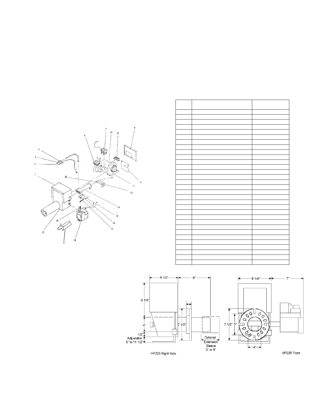
FIG. 16-1C – ADAMS GAS BURNER EXPLODED ASSLY- FIG. 16-1D ADAMS GAS BURNER PARTS LIST
HP225 BPS HP225 BPS
Ref. DESCRIPTION HP-225 BPS
1 Top Housing 7582-GN
2 Thermocouple ----------
2 Sensor Probe 12003
3 Pilot Burner J 124 DDA
4 Pilot Orifice (Nat.) 5221 (.021)
4 Pilot Orifice (Prop.) 3215 (.015)
5 Ignition System EPI-100 or EPI
6 Transformer (20 V.A.)
7 Relay R 8222 A 1002
8 Terminal Block 7586-3
9
7582 A
10 Bottom Access Door 7587 B
11 Slide Tray Assembly 7586 D
12 Manifold 7015 D-6
13 Pedestal (Not Shown) 7584
14 Burner Casting 7583-1
15 Insulating Boot 846
16 Pilot Shield 12005
17 Electrode (3 inch) 7583-5A
18 Combination Valve (Nat.) SX 242 NS
18 Combination Valve (Prop.) SX 242 LS
19 Pipe Nipple 50001-6-3 ½
20 Main Orifice (Specify Size) 172
21
Adjustable Orifice Assembly
6481
22 Bottom Housing Assembly 7581 B
23 Mounting Flange (Optional) 7585
24 Motor/Blower Assembly 7586-2A
25
----------
26 Extension Sleeve (Not Shown) 7581-1A-BL
27 Ignition Wire (30 inch) 7803
28 Sensor Wire (30 inch) 7852-2
 Loading...