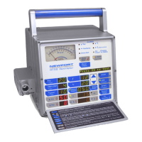
DESCRIPTION OF CONTROLS, INDICATORS, ALARMS & CONNECTIONS
3-24 SERHT50NA A0808
Alarm and Caution Messages:
All alarms have corresponding messages in the Message Display
Windo
w. See pg 2-3 for list of alarms. If more than one alarm is
violated, they are displayed in order of medical priority. Alarm
messages override the display of monitored parameters.
Setting Limitation Messages:
The following “Setting Limitation” messages are displayed to notify
the user that adjustments ha
ve caused parameters to reach
software defined limitations.
Reached Max V
•
: maximum V
•
(flow) setting has been reached
Reached Min V
•
: minimum V
•
(flow) setting has been reached
Inverse I:E: inverse I:E ratio has been reached
Reached Max I:E: inverse I:E ratio has reached 3:1
V
•
Unavailable: V
•
display is not available in Pressure Control
Peep + PS Too High: set PEEP + Psupport is higher than 60
PC – Peep Too Low: Pressure Control value minus PEEP is less
than 5 cmH
2
O/mbar
q – PEEP Too Low: High Pressure alarm limit minus PEEP is
less than 5 cmH
2
O/mbar
The following messages are provided as “prompts” or reminders.
Panel Locked: notifies user that the front panel buttons are
now locked
PRESS AGAIN: notifies user that a second press on the
same button is required in order to confirm
change requested
LEFT SIDE CONNECTORS
WARNING The round heater for the optional humidifier is
located near the left side connectors. This heater becomes
extremely hot when the humidifier is on. DO NOT TOUCH!
Airway Pressure Connector
Measures airway pressure. Connect the proximal pressure
sensing line of the patient breathing circuit to this fitting.
WARNING Always use an inline filter (p/n HT6004701 or
equiv
alent) at the Airway Pressure Connector to protect the
internal pressure transducers from moisture or other
contaminants.
Gas Output Connector
Supplies gas flow to the patient. Connect the patient breathing
circuit to this outlet.

 Loading...