SECTION 8
SERHT50NA A0808 8-9
FRONT PANEL BOARD REPLACEMENT
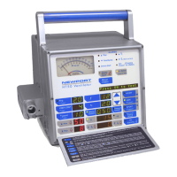
Refer to drawing Figure 9-2, Final Assembly Front View.
The Front Panel PCB should be replaced if:
• any of the front panel buttons, displays, or alarms are
malfunctioning.
• the analog meter is malfunctioning.
1. Remove the six (6) 7/64" allen screws (#49) from the Front
Panel bezel. Gently separate the bezel from the main ventilator
housing.
2. Disconnect two (2) connectors (JP1 & JP2) from the Front
Panel PCB.
3. Place the Front Panel Assembly face down on a flat surface.
Remove the ten (10) Philips head screws securing the Front
Panel PCB to the front panel plate.
NOTE: Some older HT50 units have nine (9) Phillips scre
ws
securing the Front Panel PCB to the front panel plate.
4. Remove Front Panel PCB and place it inside an anti-static bag.
5. Remove the protective plastic cover from the analog meter.
Install the new Front Panel PCB, by reversing steps 1 through 3.
FRONT PANEL BEZEL REPLACEMENT
Refer to drawing Figure 9-2, Final Assembly Front View.
The Front Panel Bezel should be replaced if:
• the bezel is cracked or dented
1. Follow steps 1 through 4 in the FRONT PANEL BOARD
REPLACEMENT section.
2. Remove the six (6) #10 torx screws securing the front panel
plate to the bezel. Gently separate the plate from the bezel.
3. To install the new Front Panel Bezel, reverse steps 1 and 2.

 Loading...