Fi
. 18
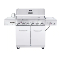
14. Side Burner Installation
a) From underneath the side burner remove
two screws which are assembled on the
bottom of the side tube burner (U). Open
side burner lid and place the Side Tube
Burner (U) through the opening. Place the
Side Tube Burner (U) tube over the side
burner gas valve and make sure Side Burner
gas valve is inserted into side burner tube.
As shown in Fig. 18.
b) Then with two screws removed in step 11a
secure the side burner from underneath to the
Side Burner Shelf (D). As shown in Fig. 18.
c) Connect ignition wire from Firebox Assembly (A)
control panel to the side burner igniter pin from
underneath the Side Burner Shelf & Control
Panel (D). As shown in Fig. 18.
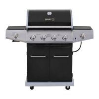
Note: After completing side burner installation,
make sure here is no more than a 3 mm gap
between igniter pin and burner. As shown in Fig. 19.
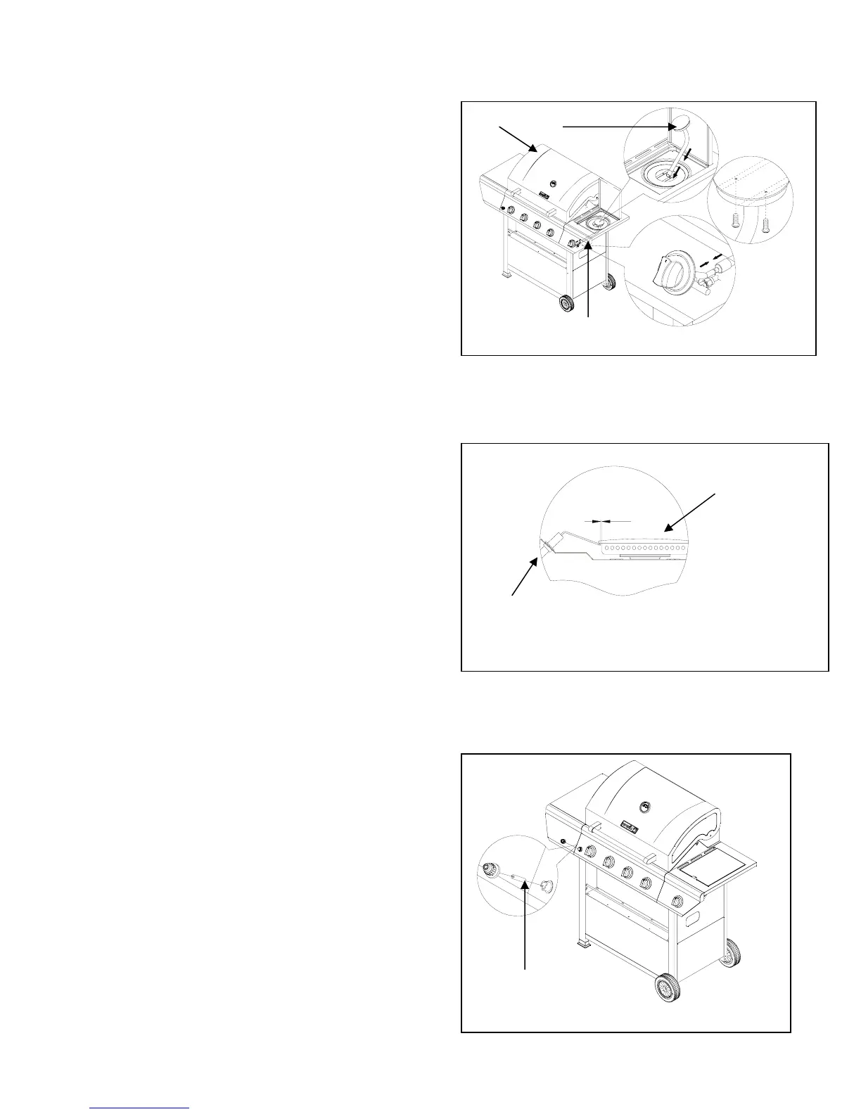
15. Electronic Igniter Battery Installation
Unscrew the electronic igniter button
and place the battery (V) into the housing
with the positive terminal (+) facing
outward. Replace the ignition button
after the battery has been installed.
As shown in Fig. 20.
Fi
. 20
Fi
. 19
3mm
Side Burner
Side Burner
Igniter Wire
3mm
A
3
5
0
2
5
0
1
5
0
5
0
F
7
0
0
6
0
0
5
0
0
4
0
0
C
3
0
0
2
00
1
0
0
5
0
15