GEO M12 HARDWARE SETUP PROCEDURE Page 39/90
- Use the levers to lock VNT-MNSTKM12 on MSUB18
- Release first GEO M12 link bar, and set AutoRig in automatic lock position
- Position first GEO M12 on top of the VNT-MNSTKM12, front points will lock automatically
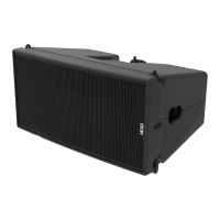
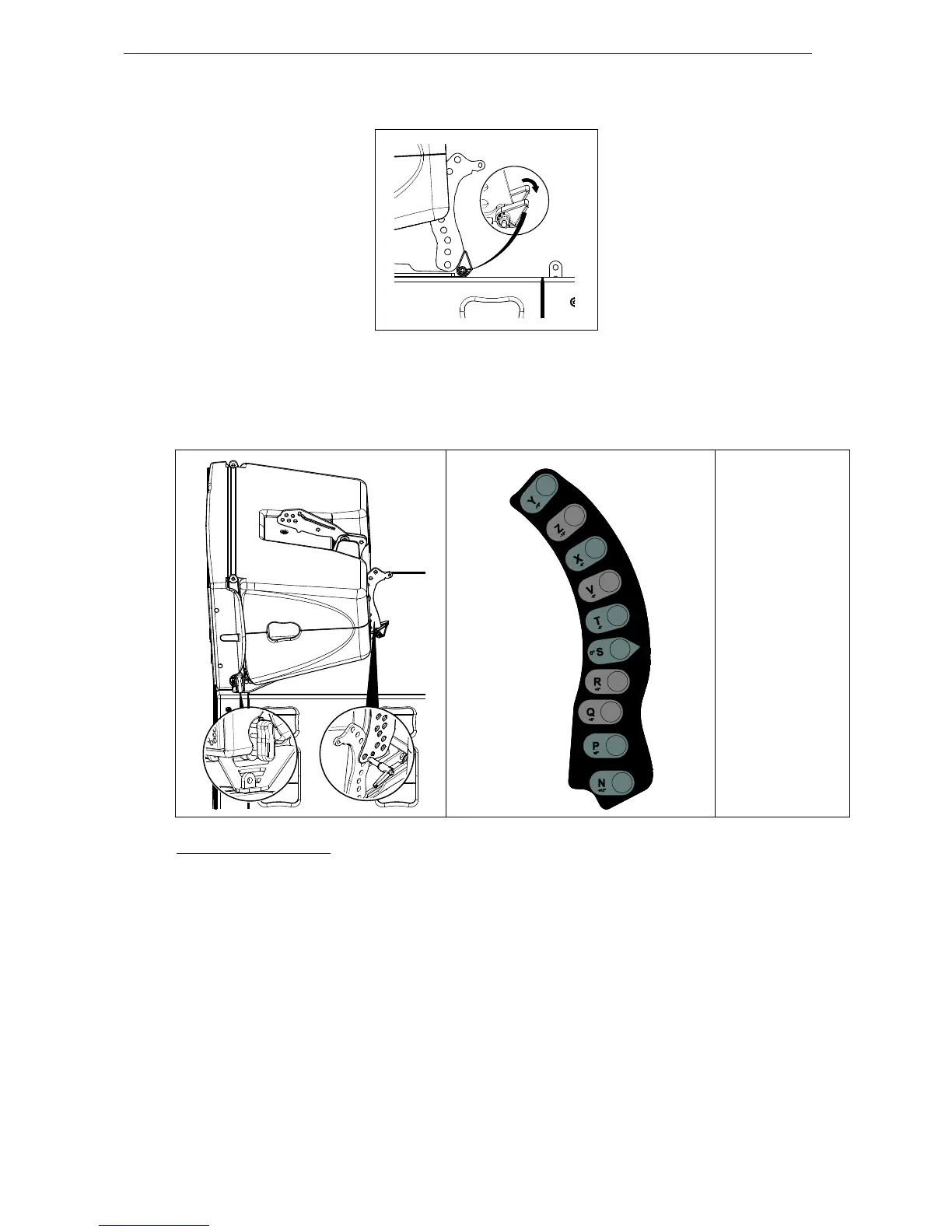
- Connect the VNT-MNSTKM12 link bar (selection from -15° to +12° in 3° steps) to GEO M12 rear
rigging plate (hole marked “bumper”) Lock with the quick release pin BL0820.
Y - 15°
Z - 12°
X - 9°
V - 6°
T - 3°
S 0°
R + 3°
Q + 6°
P + 9°
N + 12°
Subsequent GEO M12s
- Position second GEO M12 cabinet with AutoRig
TM
in automatic lock position, and lock front points to
first GEO M12
- Unlock GEO M12 link bar
- Pull the latch to engage the guide in GEO M12 rear slot.
- Adjust the angle by inserting quick release pin BL820 in proper hole.
- Connect subsequent GEO M12 cabinets as with second.
 Loading...