GEO M12 GENERAL SET-UP INSTRUCTIONS Page 9/90
2.2 GEO M12-I and MSUB18-I connections
2.2.1 GEO M12-I connectors
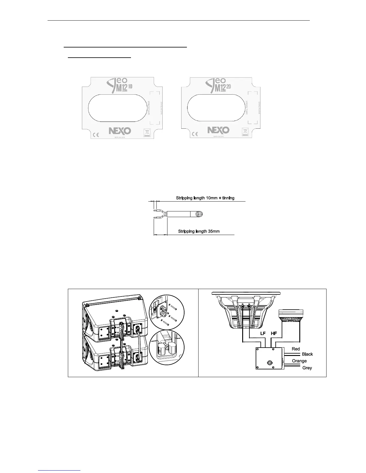
GEOM12-I are connected through 2 captive cables and 2 fast connectors.
In order to connect for installation:
- Remove the connecting plate.
- Pass the cables through the cable-gland (maximum cable outside diameter is 12mm / 0.5”, maximum
gauge wire is 2.5 mm
2
/ AWG13 for solid cable and 4 mm
2
/ AWG11 for multi-stranded cable)
- Prepare cable as below
- Connect to the fast connectors (+): Brown (or Red) / (-): Blue (or Black).
- Remount the connecting plate.
- Tight the cable-gland and adjust the length.
- Seal the cabinet with the provided blind plug on the unused cable gland.
 Loading...