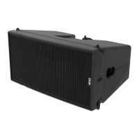
- Once last GEO M12 has been removed, unlock and remove bottom bumper
- Lower MSUB18s on the ground, unlock front and rear rigging points and lift cluster to remove bottom
MSUB18.
- Repeat until last MSUB18 is removed
- Disassemble top bumper.
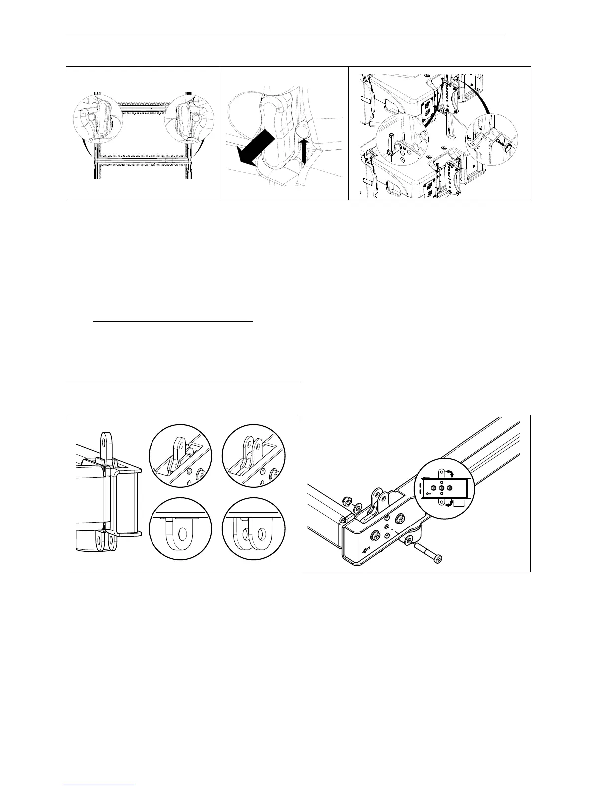
6.5 Permanent Installation variant
All procedures described above apply to installation versions, with the exception of bumper and cabinet
connections, which are described below:
Configuring VNI- BUMPM12 for GEO M12-I Left or Right
- Adjust the front rigging point to required configuration and lock with provided screws (screws M8x45,
washers M8, brake nuts M8).
 Loading...