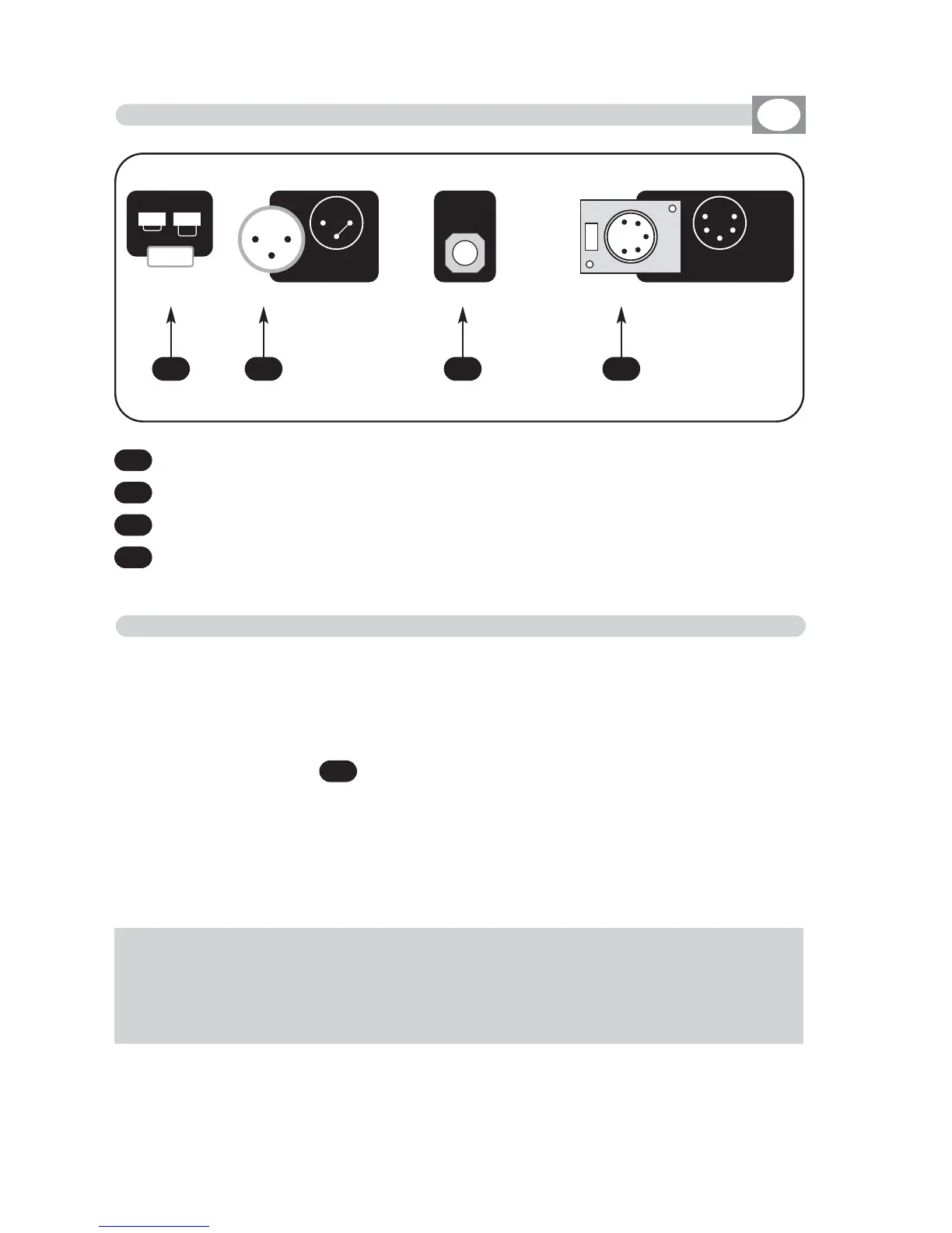
4
Standard DMX 512 signal OUTPUT with a 5-pin cannon connector.
3
0 dB audio signal INPUT with a mono/stereo jack connector.
2
12 Vdc power INPUT with a 3-pin cannon connector.
1
Power key
Make sure you are using a shielded twisted cables suitable for the tran-
smission of the DMX 512 signal with connectors of good quality and
connection as shown on the side of the connector.
Plug the 5-pin cannon connector coming from the dimmer completly in the
DMX 512 output
Use the “push” safety hook to disconnect it and than extract it gently.
ATTENTION: the shielded part of the cable must never be connected to
the ground of the electrical system as this could cause faults during the
working of the controller.
4
1 2 3 4
2.1 Description of the rear panel and installation
GB
2.2 DMX 512 OUTPUT CONNECTION
THE DMX CHANNEL OUT ARE:
N° 1/24 DOUBLE PRESET MODE
N° 1/48 SINGLE PRESET MODE (WIDE)