CONNECTION OF SENSORS AND EXTERNAL
ADJUSTMENT
For the location of the terminal blocks, see Component
location, AXC module (AA25) page 5.
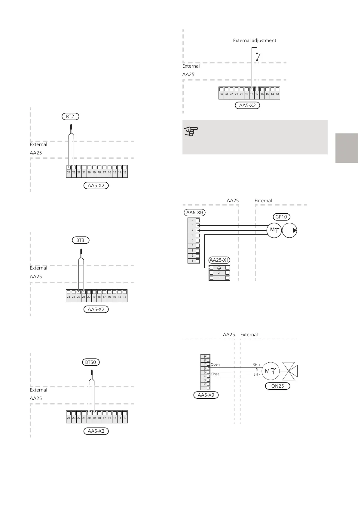
SUPPLY TEMPERATURE SENSOR, EXTRA
CLIMATE SYSTEM (BT2)
Connect the supply temperature sensor to AA5-X2:23-
24.
24 23 22 21 20 19 18 17 16 15 14 13
RETURN LINE SENSOR, EXTRA CLIMATE
SYSTEM (BT3)
Connect the return line sensor to AA5-X2:21-22.
24 23 22 21 20 19 18 17 16 15 14 13
ROOM SENSOR, EXTRA CLIMATE SYSTEM
(BT50) (OPTIONAL)
Connect the room sensor to AA5-X2:19-20.
24 23 22 21 20 19 18 17 16 15 14 13
EXTERNAL ADJUSTMENT (OPTIONAL)
A potential-free switch can be connected to AA5-X2:17-
18 for external adjustment of the climate system.
24 23 22 21 20 19 18 17 16 15 14 13
AA25
External
AA5-X2
External adjustment
Caution
The relay outputs on the accessory board can
have a max load of 2 A (230 V) in total.
CONNECTION OF THE CIRCULATION PUMP
(GP10)
Connect the external heating medium pump (GP10) to
AA5-X9:7 (N), AA5-X9:8 (230 V) and X1:PE.
1
2
3
4
5
6
7
8
9
AA5-X9
2
1
1
M
AA25-X1
CONNECTION OF THE SHUNT VALVE
MOTOR (QN25)
Connect the shunt motor (QN25) to AA5-X9:6 (230V,
open), AA5-X9:5 (N) and AA5-X9:4 (230V, close).
AA25
External
AA5-X9
QN25
Open
SH +
N
SH -
Close
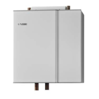
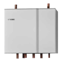
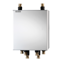
15ECS 40/ECS 41 S-series | GB
S
 Loading...