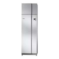
List of components
PIPE CONNECTIONS
Cold water connectionXL3
Hot water connectionXL4
Connecting incoming airXL43
Connecting outgoing airXL44
Connection, safety valveXL48
HVAC COMPONENTS
Safety valve, water heaterFL1
Vacuum valve (only F110 copper)FL6
Mixer valve, hot waterFQ1
Charge pumpGP12
Venting screw (only F110 stainless steel)QM5
Vent valve, hot waterQM25
Shut-off valve, hot waterQM30
Connection areaQQ4
Overflow cupWM1
Overflow water dischargeWM2
SENSORS
High pressure pressostatBP1
Temperature sensor, hot water, controlBT6
Temperature sensor, hot water, displayBT7
Temperature sensor, condenser outBT12
Temperature sensor, heating medium return before
condenser
BT13
Temperature sensor, evaporatorBT16
ThermostatBT35
Temperature sensor, defrostingBT76
Temperature sensor, incoming airBT77
ELECTRICAL COMPONENTS
Base cardAA2
Display unitAA4
CapacitorCA1
Immersion heaterEB1
Compressor heaterEB10
Temperature limiterFQ10
COOLING COMPONENTS
EvaporatorEP1
CondenserEP2
CompressorGQ10
Drying filterHZ2
Expansion valveQN1
Solenoid valve, defrostingQN20
VENTILATION
FanGQ1
Air filter
1
HQ12
MISCELLANEOUS
Rating platePZ1
Serial number platePZ3
Designations according to standard EN 81346-2.
1
Not visible in the image.
NIBE F110Chapter 3 | The Heat pump design12

 Loading...