General
Pipe installation must be carried out in accordance with
current norms and directives. F1145 can operate with a
return temperature of up to 58 °C and an outgoing
temperature from the heat pump of 70 (65 °C with only
the compressor).
F1145 is not equipped with external shut off valves; these
must be installed to facilitate any future servicing.
NOTE
The pipe system needs to be flushed out before
the heat pump is connected so that debris can-
not damage component parts.
NOTE
This installation is subject to building regulation
approval, notify the local Authority of intention
to install.
NOTE
Use only manufacturer’s recommended replace-
ment parts.
Symbol key
MeaningSymbol
Venting valve
Shut-off valve
Non-return valve
Shunt / shuttle valve
Safety valve
Trim valve
Tundish
Temperature sensor
Level vessel
Pressure gauge
P
Circulation pump
Particle filter
Auxiliary relay
Fan
Compressor
Heat exchanger
Hard water areas
Usually, there should not be a problem in installing F1145
in areas of hard water as the maximum operating temper-
ature is 60 °C.
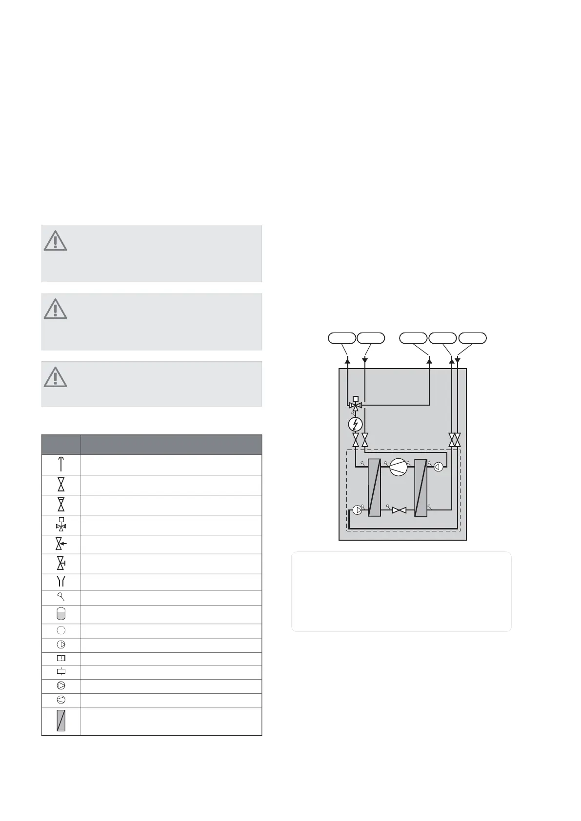
System diagram
F1145 consists of heat pump, immersion heater, circula-
tion pumps and control system. F1145 is connected to
the brine and heating medium circuits.
In the heat pump evaporator, the brine (water mixed with
anti-freeze, glycol or ethanol) releases its energy to the
refrigerant, which is vaporised in order to be compressed
in the compressor. The refrigerant, of which the temper-
ature has now been raised, is passed to the condenser
where it gives off its energy to the heating medium circuit
and, if necessary, to any docked water heater. If there is
a greater need for heating/hot water than the compressor
can provide there is an integrated immersion heater.
;/ ;/ ;/ ;/;/
Connection, heating medium flowXL 1
Connection, heating medium returnXL 2
Connection, brine inXL 6
Connection, brine outXL 7
Connection, hot water heaterXL 9
11Chapter 4 | Pipe connectionsNIBE™ F1145
4 Pipe connections

 Loading...


