30 Complete the start guide
VWDUW JXLGH
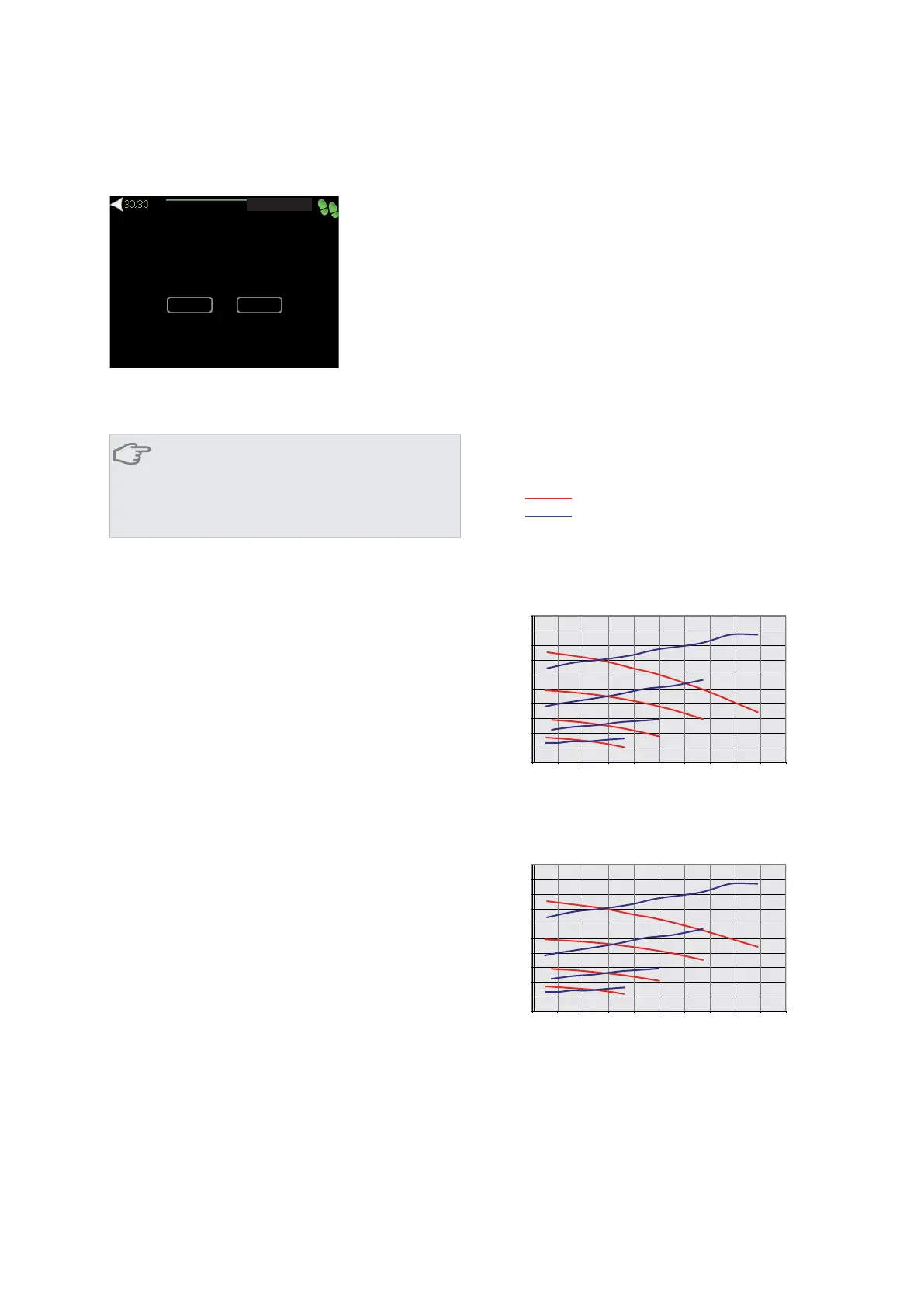
<RX KDYH FRPH WR WKH ODVW SDJH RI WKH VWDUW
JXLGH 'R \RX ZLVK WKH VWDUW JXLGH WR VWDUW WKH
QH[W WLPH WKH KHDW SXPS LV UHVWDUWHG"
QR
\HV
Here you select whether to start the start guide the next
time the heat pump is restarted.
Caution
If you choose "yes" this means that the next
time the heat pump is started (e.g. after a power
cut) it will not produce heat or hot water for 60
minutes.
Post adjustment and venting
Pump capacity diagrams, collector side
To set the correct flow in the brine system the correct
speed must be set for the brine pump.
The flow must have a temperature difference between
brine out (BT11) and brine in (BT10) of2-5°Cwhen the
system is balanced (suitably 5 minutes after compressor
start). Check these temperatures in menu 3.1 "service
info" and adjust the brine pump (GP2) speed until the
temperature difference is achieved. A high difference in-
dicates a low brine flow and a low difference indicates a
high brine flow.
Read off what speed the brine pump should have from
the diagrams below.
Eleffekt
Tillgängligt tryck
P
$YDLODEOH SUHVVXUH
(OHFWULFDO RXWSXW
F1145 5 kW
0
10
20
30
40
50
60
70
80
90
100
0 0,05 0,10 0,15 0,20 0,25 0,30 0,35 0,40 0,45 0,50
Tillgängligt tryck, kPa / Eleffekt, W
Flöd
l/s
P100%
100%
P80%
80%
P60%
60%
P40%
40%
OV
)ORZ
$YDLODEOH SUHVVXUH N3D
(OHFWULFDO RXWSXW :
F1145 8 kW
0
10
20
30
40
50
60
70
80
90
100
0 0,05 0,10 0,15 0,20 0,25 0,30 0,35 0,40 0,45 0,50
Tillgängligt tryck, kPa / Eleffekt, W
Flöd
l/s
P100%
100%
P80%
80%
P60%
60%
P40%
40%
OV
)ORZ
$YDLODEOH SUHVVXUH N3D
(OHFWULFDO RXWSXW :
NIBE™ F1145Chapter 6 | Commissioning and adjusting36

 Loading...


