SYMBOL KEY
MeaningSymbol
Unit box
Shut-off valve
Non-return valve
Circulation pump
Expansion vessel
Filterball
Fan
Pressure gauge
Level vessel
Particle filter
Safety valve
Temperature sensor
Reversing valve/shunt
Manual reversing valve/shunt
Heat exchanger
Overflow valve
Bore hole
Ground collector
Under floor heating systems
Heat pump
Cooling system
Pool
Radiator system
Domestic hot water
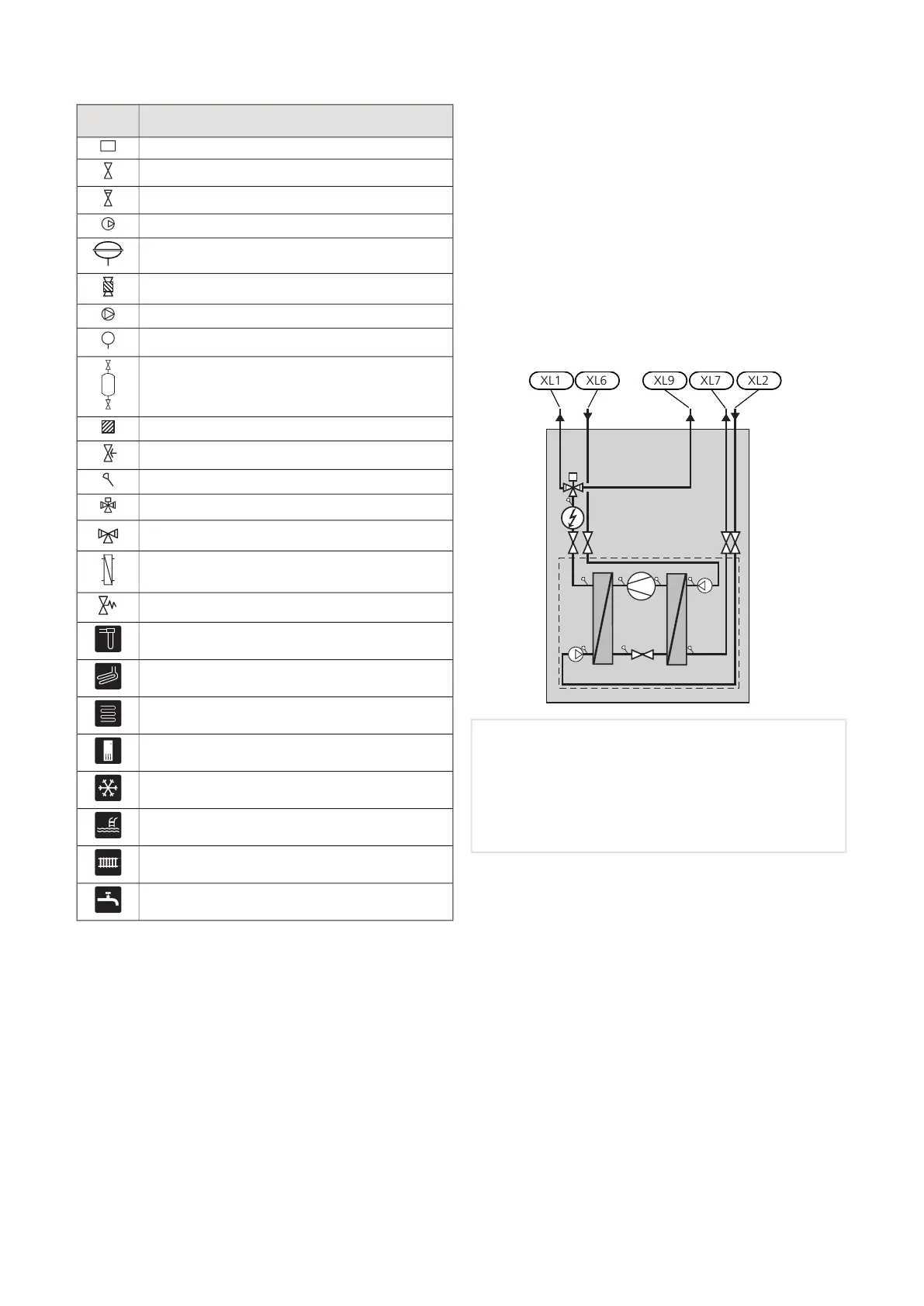
SYSTEM DIAGRAM
F1155 consists of heat pump, immersion heater, circu-
lation pumps and control system. F1155 is connected
to the brine and heating medium circuits.
In the heat pump evaporator, the brine (water mixed
with anti-freeze, glycol or ethanol) releases its energy
to the refrigerant, which is vaporised in order to be
compressed in the compressor. The refrigerant, of which
the temperature has now been raised, is passed to the
condenser where it gives off its energy to the heating
medium circuit and, if necessary, to any docked water
heater. If there is a greater need for heating/hot water
than the compressor can provide there is an integrated
immersion heater.
Connection, heating medium flowXL1
Connection, heating medium returnXL2
Connection, brine inXL6
Connection, brine outXL7
Connection, hot water heaterXL9
15Chapter 4 | Pipe connectionsNIBE F1155

 Loading...


