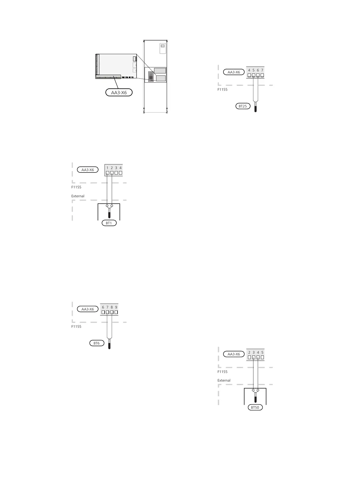
CONNECTING SENSORS
Connect the sensor(s) to
terminal X6 on input
board(AA3) according to
the instructions below.
Outside sensor
Install the outdoor tem-
perature sensor (BT1) in
the shade on a wall fa-
cing north or north-west,
so it is unaffected by the
morning sun for example.
Connect the sensor to terminal block X6:1 and X6:2 on
the input board (AA3).
If a conduit is used it must be sealed to prevent condens-
ation in the sensor capsule.
Temperature sensor, hot water charging
The temperature sensor, hot water charging (BT6) is
placed in the submerged tube on the water heater.
Connect the sensor to terminal block X6:7 and X6:8 on
the input card (AA3). Use a 2 core cable of at least 0.5
mm² cable area.
Hot water charging is activated in menu 5.2 or in the
start guide.
Temperature sensor, hot water top
A temperature sensor for hot water top (BT7) can be
connected to F1155 via soft inputs for showing the
water temperature at the top of the tank.
The temperature sensor, hot water top (BT7) is connec-
ted to the selected input (menu 5.4, see page 26) on
terminal block X6 on the input card (AA3) which is loc-
ated behind the front cover and in a submerged tube on
the water heater.
Temperature sensor, external flow line
If temperature sensor, external supply line (BT25) needs
to be used, connect it to terminal block X6:5 and X6:6
on the input board (AA3).
Room sensor
F1155 is supplied with a room sensor enclosed (BT50).
The room sensor has a number of functions:
1.
Shows current room temperature in the display on
F1155.
2.
Option of changing the room temperature in °C.
3.
Provides the option of fine-tuning the room temper-
ature.
Install the sensor in a neutral position where the set
temperature is required. A suitable location is on a free
inner wall in a hall approx. 1.5 m above the floor. It is
important that the sensor is not obstructed from meas-
uring the correct room temperature by being located,
for example, in a recess, between shelves, behind a
curtain, above or close to a heat source, in a draft from
an external door or in direct sunlight. Closed radiator
thermostats can also cause problems.
The heat pump operates without the sensor, but if one
wishes to read off the accommodation's indoor temper-
ature in F1155's display, the sensor must be installed.
Connect the room sensor to X6:3 and X6:4 on the input
board (AA3).
If the sensor is to be used to change the room temper-
ature in °C and/or to fine-tune the room temperature,
the sensor must be activated in menu 1.9.4.
If the room sensor is used in a room with underfloor
heating, it should only have an indicatory function, not
control of the room temperature.
23Chapter 5 | Electrical connectionsNIBE F1155

 Loading...


