15
14
13
15
14
13
15
14
13
A
B
GND
A
B
GND
AA3-X4
A
B
GND
AA3-X4
A
B
GND
A
B
GND
AA3-X4
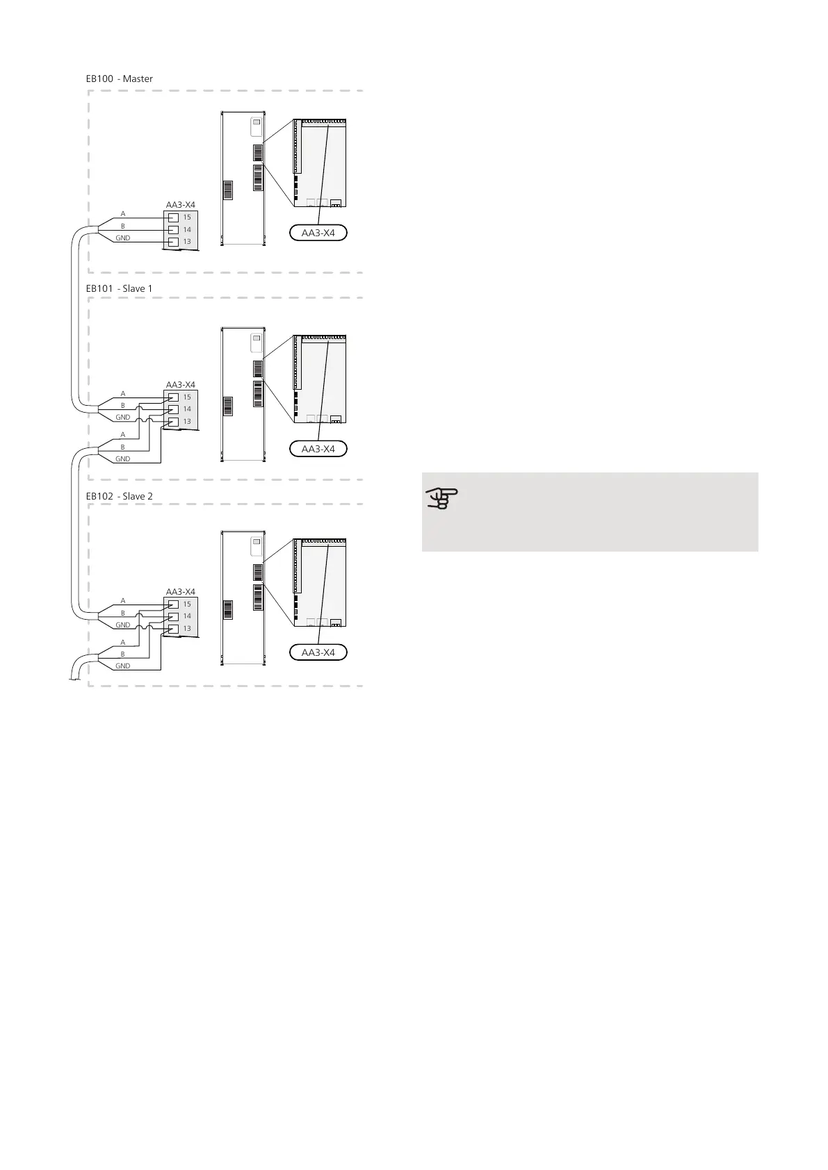
EB100 - Master
EB101 - Slave 1
EB102 - Slave 2
LOAD MONITOR
Integrated load monitor
F1245 is equipped with a simple form of integrated load
monitor, which limits the power steps for the electric
additional heat by calculating whether future power
steps can be connected to the relevant phase without
exceeding the specified main fuse. If the current would
exceed the specified main fuse, the power step is not
permitted. The size of the property’s main fuse is spe-
cified in menu 5.1.12.
Load monitor with current sensor
When many power-consuming products are connected
in the property at the same time as the electric additional
heat is operating, there is a risk that the property’s main
fuse will trip. F1245 is equipped with a load monitor
that, with the help of a current sensor, controls the
power steps for the electric additional heat by redistrib-
uting the power between the different phases or disen-
gages the electric additional heat if there is an overload
in a phase. Reconnection occurs when the other current
consumption drops.
Caution
Activate phase detection in menu 5.1.12 for
full functionality, if current sensors are installed.
Connecting current sensors
A current sensor should be installed on each incoming
phase conductor in to the distribution box to measure
the current. The distribution box is an appropriate install-
ation point.
Connect the current sensors to a multi-core cable in an
enclosure directly adjacent to the electrical distribution
unit. The multi-core cable between the enclosure and
F1245 must have a cable area of at least 0.5 mm².
27Chapter 5 | Electrical connectionsNIBE F1245

 Loading...


