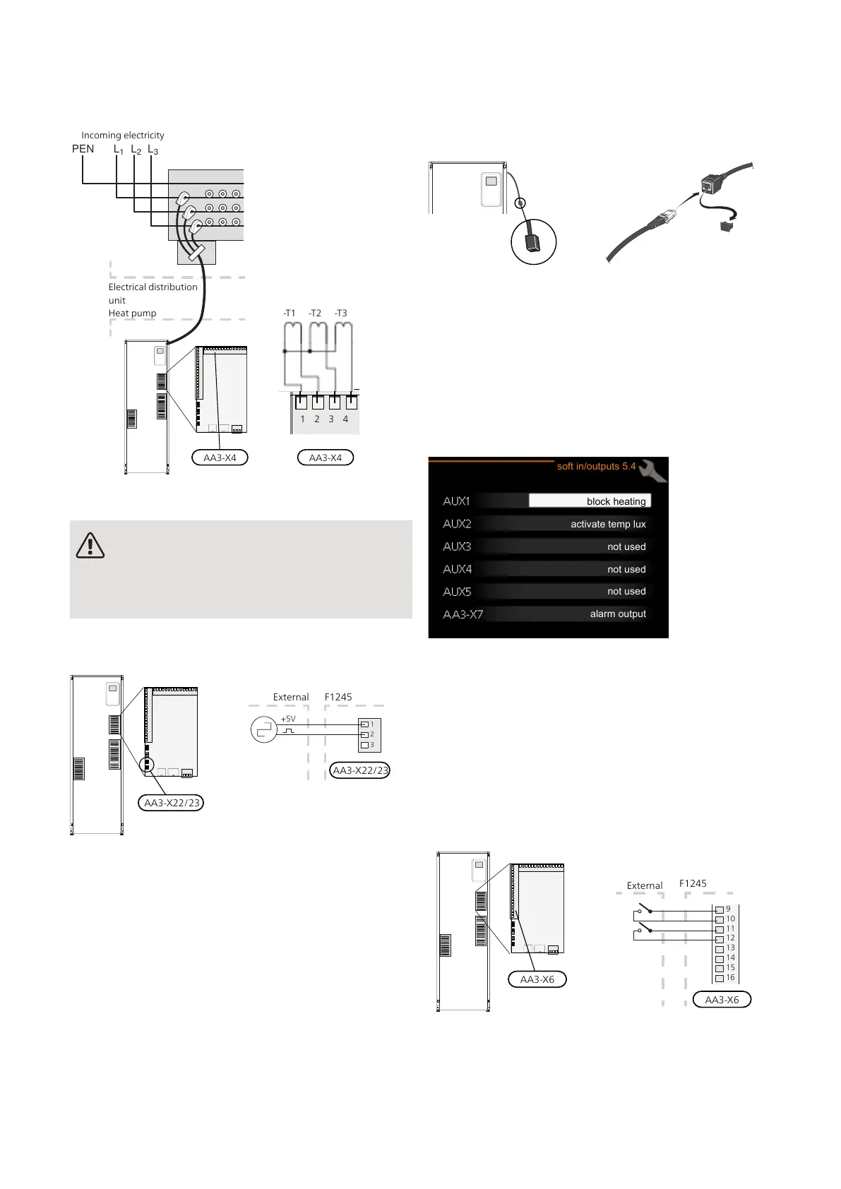
Connect the cable to the input board (AA3) on terminal
block X4:1-4 where X4:1 is the common terminal block
for the three current sensors.
AA3-X4 AA3-X4
Electrical distribution
unit
Heat pump
Incoming electricity
1 2 3 4
-T1 -T2 -T3
CONNECTING EXTERNAL ENERGY METER
NOTE
Connection of external energy meter requires
version 35 or later on input board (AA3) as well
as "display version" 7113 or later.
One or two energy meters (BE6, BE7) are connected to
terminal block X22 and/or X23 on input board (AA3).
1
2
3
P
roduktNamn
Extern energimätare
+5V
Activate the energy meter(s) in menu 5.2.4 and then set
the desired value (energy per pulse) in menu 5.3.21.
NIBE UPLINK
Connect the network connected cable (straight, Cat.5e
UTP) with RJ45-contact (male) to RJ45 contact (female)
on the rear of the heat pump.
EXTERNAL CONNECTION OPTIONS
F1245 has software-controlled AUX inputs and outputs
on the input board (AA3), for connecting the external
switch function or sensor. This means that when an
external switch function (the switch must be potential-
free) or sensor is connected to one of six special con-
nections, this function must be selected for the correct
connection in menu 5.4.
block heating
activate temp lux
not used
not used
not used
alarm output
soft in/outputs 5.4
For certain functions, accessories may be required.
Selectable inputs
Selectable inputs on the input board for these functions
are:
AA3-X6:9-10AUX1
AA3-X6:11-12AUX2
AA3-X6:13-14AUX3
AA3-X6:15-16AUX4
AA3-X6:17-18AUX5
F1245Externt
9
10
11
12
13
14
15
1
6
B
A
The example above uses the inputs AUX1 (X6:9-10) and AUX2 (X6:11-
12) on the input board (AA3).
Selectable output
A selectable output is AA3-X7.
NIBE F1245Chapter 5 | Electrical connections28

 Loading...


