TEMPERATURE SENSOR DATA
Voltage (VDC)Resistance
(kOhm)
Temperature (°C)
3.256351.0-40
3.240251.6-35
3.218182.5-30
3.189133.8-25
3.15099.22-20
3.10574.32-15
3.04756.20-10
2.97642.89-5
2.88933.020
2.78925.615
2.67320.0210
2.54115.7715
2.39912.5120
2.24510.0025
2.0838.04530
1.9166.51435
1.7525.30640
1.5874.34845
1.4263.58350
1.2782.96855
1.1362.46760
1.0072.06865
0.8911.73970
0.7851.46975
0.6911.24680
0.6071.06185
0.5330.90890
0.4690.77995
0.4140.672100
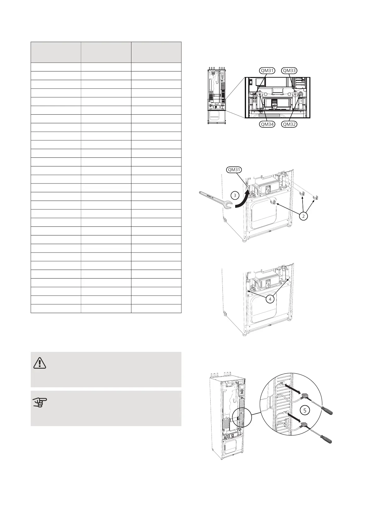
PULLING OUT THE COOLING MODULE
The cooling module can be pulled out for service and
transport.
NOTE
Switch off the heat pump and cut the power
with the safety switch.
Caution
Remove the front cover according to the de-
scription on page 8.
1.
Close the shut-off valves (QM31), (QM32), (QM33)
and (QM34).
Drain the compressor module according to the in-
structions on page 60
2.
Pull off the lock catches.
3.
Disconnect the pipe connection under the shut-off
valve (QM31).
4.
Remove the two screws.
5.
Remove the connections from the base card (AA2)
using a screwdriver.
6.
Disconnect the connectors (A) and (B) from the un-
derside of the base card cabinet.
NIBE F1245Chapter 9 | Service62

 Loading...


