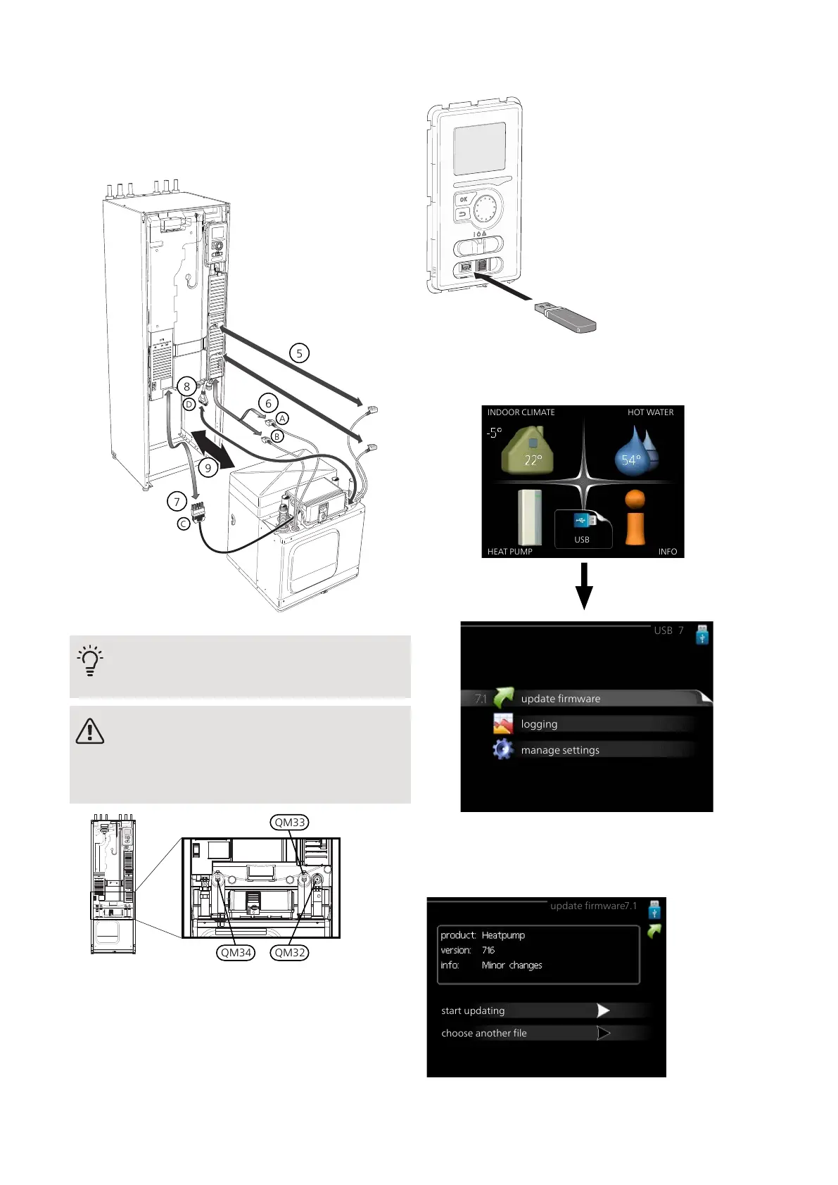
7.
Disconnect the connector (C) from the electric addi-
tion PCB (AA1) using a screwdriver.
8.
Disconnect the switch (D) from the joint board
(AA100).
9.
Carefully pull out the cooling module.
TIP
The cooling module is installed in reverse order.
NOTE
At reinstallation, the supplied O-rings must re-
place the existing ones at the connections to
the heat pump (see image).
USB SERVICE OUTLET
The display unit is equipped with a USB socket that can
be used to update the software and save logged inform-
ation in F1245.
INDOOR CLIMATE
HEAT PUMP INFO
HOT WATER
USB
update firmware
USB 7
logging
manage settings
When a USB memory is connected, a new menu (menu
7) appears in the display.
Menu 7.1 - update firmware
update firmware7.1
start updating
choose another file
This allows you to update the software in F1245.
63Chapter 9 | ServiceNIBE F1245

 Loading...


