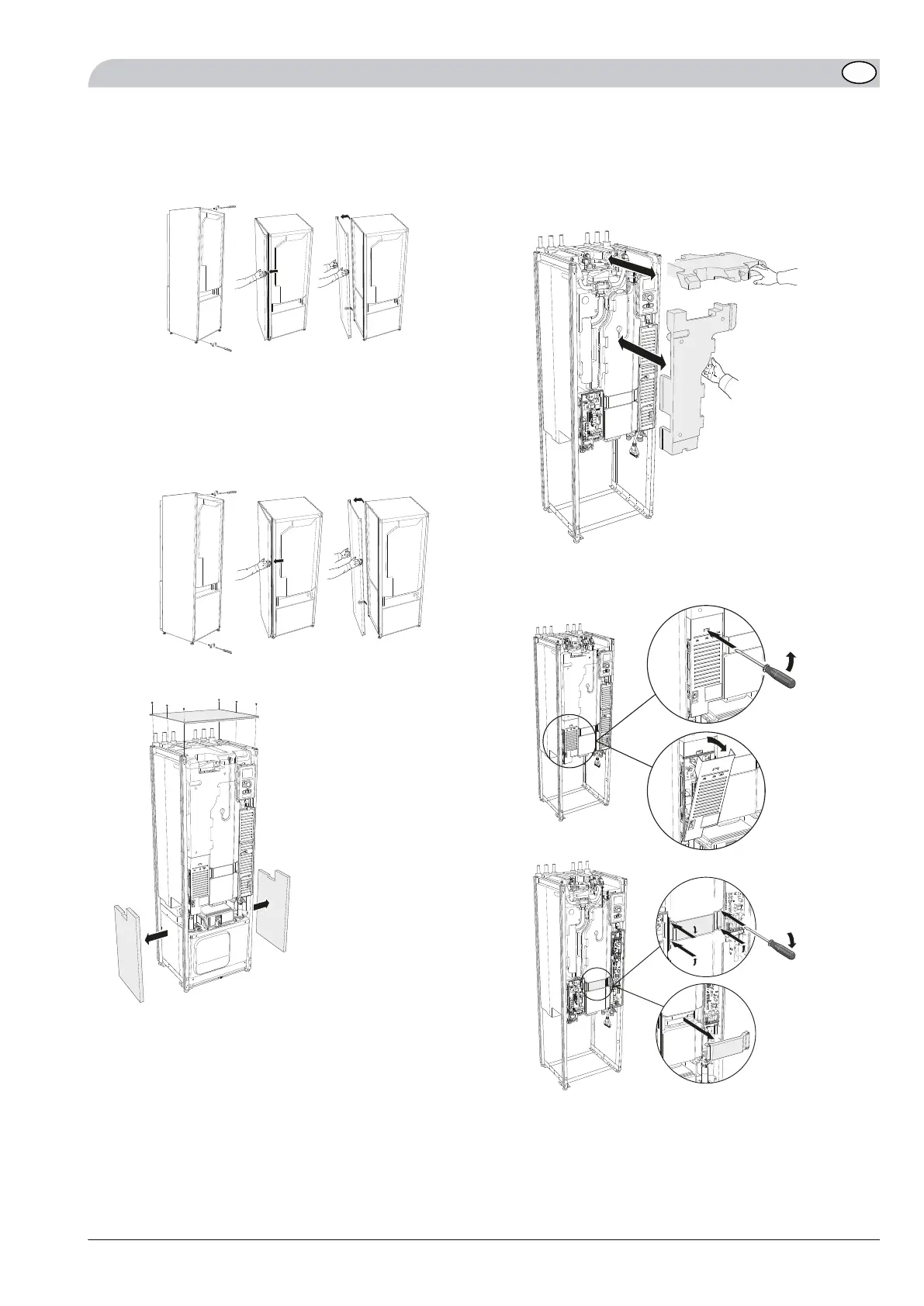
6.
If necessary pull the heat pump forward.
7.
Remove side covers, top panel and sound insulation
sheets in the stand frame between the cooling module
and side covers.
LEK
LEK
LEK
A
Remove the screws from the upper and lower
edges.
B
Twist the cover slightly outward.
C
Move the hatch outwards and backwards.
D
Assembly takes place in the reverse order.
LEK
LEK
LEK
LEK
Left junction box and immersion heater, trans-
ferring
1.
Remove the top insulation above the heater and in
front of the immersion heater, both on the old and
the new unit.
LEK
2.
Remove the protective cover of the junction box and
the plastic cover between the right and left junction
boxes.
LE
K
1.
2.
A
B
LEK
A
B
1.
2.
3.
4.
15NIBE F1245/F1255
GB
 Loading...


