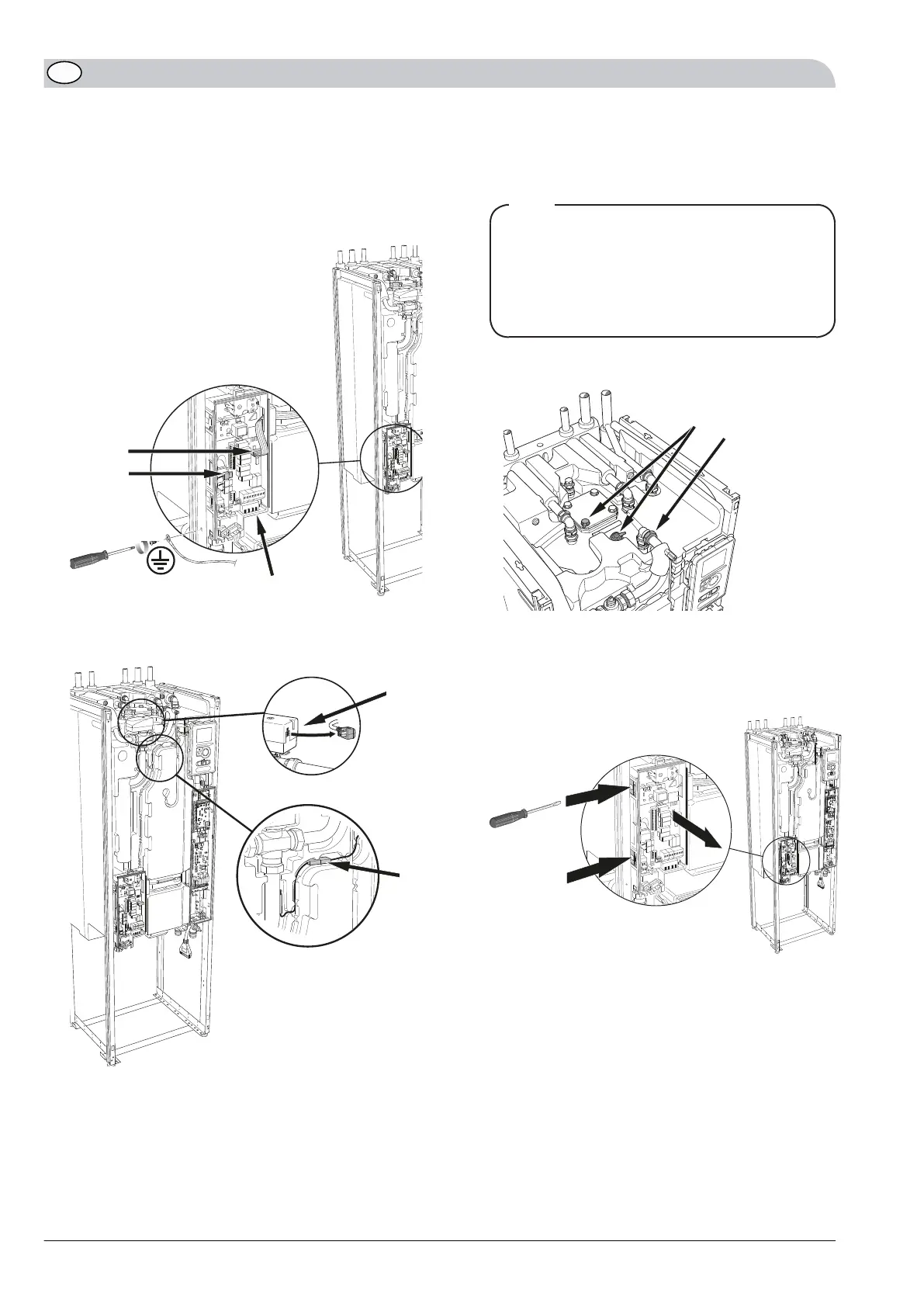
3.
Disconnect/remove the ribbon cable from the immer-
sion heater circuit board.
4.
Disconnect/remove the wiring connector.
5.
Disconnect/remove the wiring connector (screwdriver).
6.
Disconnect/remove the ground cable secured on the
left hand side of the stand frame.
LE
K
4.4?
4.3?
4.6?
3
4
5
6
7.
Disconnect/remove the connector from sensor (BT2).
8.
Disconnect/remove the connector from the reversing
valve (QN10).
LEK
7
8
9.
Only applies to enamelled heaters:
Disconnect/remove the cable connectors from the
anode.
TIP
Important!
Note the positions of the cables.
If the cables are connected in the wrong position
the corrosion protection will be absent when re-
installed.
10.
Loosen the nut on the HM supply line to the charge
coil on the heater to the air valve (QM22).
10
9
9
10
11.
Remove the pipe clamps on the HM supply line
between the immersion heater and the cooling mod-
ule (QM31) and separate the connector.
12.
Disconnect/remove the junction box from its mount-
ings.
L
EK
Press
Press
A
B
NIBE F1245/F125516
GB
 Loading...


