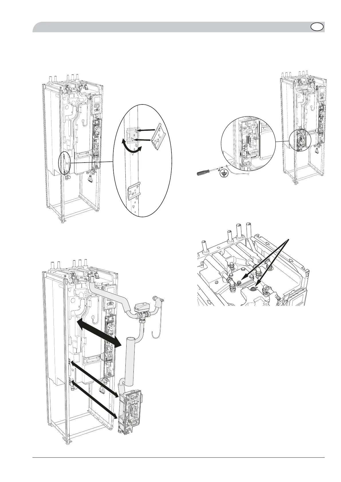
13.
Install two new mountings (supplied) for the junction
box on the new unit's left stand frame. Each mount-
ing has two mounting pins that are inserted in the
frame and then twisted to secure it.
L
EK
A
B
14.
Install the Conex angle (supplied) on the supply line
to the charge coil on the new unit.
15.
Transfer the whole package (immersion heater and
junction box) to the new unit. (Angle out the immer-
sion heater and hold the junction box.)
L
EK
16.
Secure the junction box in the quick mountings, the
ground cable in the stand frame and tighten the con-
nection to the charge coil.
LE
K
17.
Only applies to enamelled heaters:
Connect the cables to the anode. It is important that
these are connected in the correct positions, if incor-
rectly connected the corrosion protection is absent.
17
17
17NIBE F1245/F1255
GB
 Loading...


