Assembly
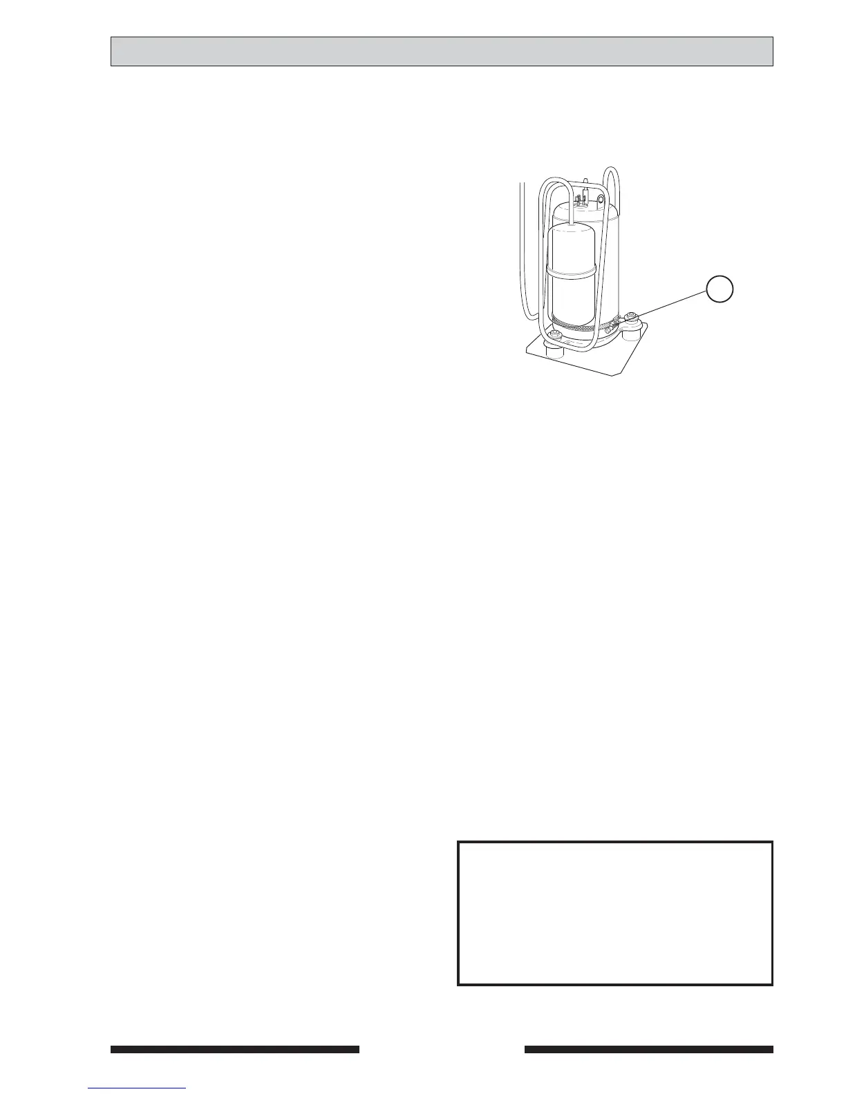
The compressor heater prevents a large amount of
cooling agent from collecting in the compressor during
downtime. Mount the crankcase heater (68) around the
compressor as shown in the adjoining figure after
removing the fan. Ensure the heater is not touching
any cooling tubes.
■ Pull the heater’s cable through one of the inlets
on the vertical plate to the right of the fan.
■ Pull the heater’s cable through the pull-relief
clamp on the electrical connection plate.
FIGHTER 310P and 315P:
■ Drill a hole (Ø 3,2 mm) to the left of
the above pull-relief clamp and rivet the
accompanying earth branch pin and locking
washer if not already mounted.
■ Connect the cable ends (use the accompanying
cable set if required) in the electrical connection
area as follows, see also electric circuit diagram
pages 4, 5, and 6:
• Yellow/green cable to the earth branch pin to
the left of the pull relief clamp.
• Blue cable to position A2 on the contactor (10).
Use the accompanying branch if required.
• Brown cable to position 5 on the switch (8).
Use the accompanying branch if required.
KV- FIGHTER 200P/310P/315P
PLEASE NOTE!
Electrical installation must be carried
out by a qualified electrician and must
be in accordance with the stipulations
in force.
 Loading...


