7
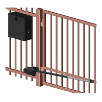
6.4 - Step four-manual release
Having removed the top cover, locate the manual release handle. Insert and
turn the manual release handle clockwise until the turret assembly is loose
and moves freely. The main drive assembly is now disengaged and the gate
turret may be operated by hand.
Figure 6 - MANUAL RELEASE
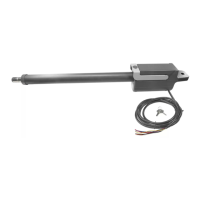
6WHSƄYHDUPDVVHPEO\
Connect the main arm assembly to turret assembly and test gate for free
movement. (Should move freely in both directions) Push the gate by hand to
the full movement in each direction to ensure it does not bind or catch in any
manner. Connect gate arm to gate bracket. Connect bracket to gate. Put
the gate in fully closed position and placed bracket against gate with arms
completely straightened. Gate operator should now be wired, installed and
connected to the gate.
Figure 7 - BRACKET
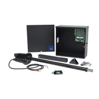
6.1 - Step one-location
Locate the area in which the opener shall be located.
6.2 - Step two-concrete
%@AQHB@SD@BNMBQDSDO@CRSQTBSTQDRTEjBHDMSSNRS@AHKHYD@MCLNTMSSGDF@SD
opener. Please consult the local building dept. and/or a structural engineer to
ATHKC@BNMBQDSDO@CSG@SLDDSRATHKCHMFBNCDR@MCHRRTEjBHDMSENQSGDRNHK
type and climate.
6.3 - Step three-physical mounting
Drill and insert RedHead (1/2” x 3 1/3”) concrete anchors into the concrete
RTEjBHDMSSNOQNODQKXLNTMSSGDF@SDNODMDQ,NTMSHMFONRHSHNMLTRSAD@
minimum distance of 21 inches distance between the gate and any obstruc-
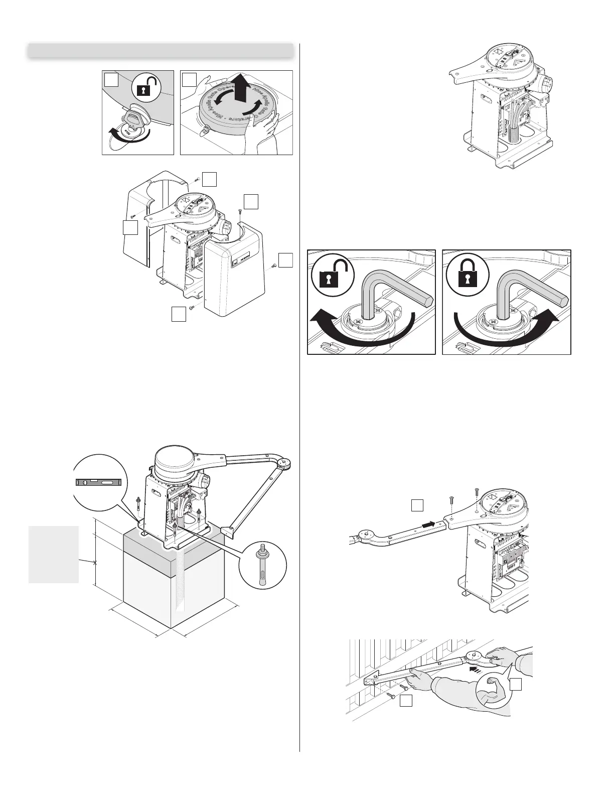
tions as shown to the left. Open the top cover using the supplied key. Remove
SGDSNO@MCRHCDBNUDQRSNF@HM@BBDRRSNLNTMSHMFGNKDR2DDjFTQD2DS
the unit in place and attach wiring as indicated in the wiring section 9.0 wiring
@MCBNMMDBSHNMRNESGHRL@MT@KRDDjFTQD
6 - INSTALLATION PROCEDURES
Remove side bolts
and covers to
access interior for
installation.
1. Remove top
cover assembly by
unlocking the lid
with the supplied
key.
2. Turn lid counter-
clockwise then
remove.
1 2
3
3
1
2
2
1
2
3
6”
24”
20”
x 4
Figure 3 - COVER REMOVAL
BELOW
THE FROST
LINE CHECK
ALL LOCAL
CODES (30”)
Figure 4
SAMPL$+ 8.43
MAKE SURE ALL POWER IS DIS-
CONNECTED PRIOR TO ANY
SERVICE OR INSTALLATION.
Figure 5 - WIRING