Do you have a question about the Nice Apollo 1500 and is the answer not in the manual?
Crucial pre-installation instructions and understanding of the manual for safe and proper operation.
Details on electrical, performance, and dimensional data for models 1500/1600 gate openers.
Conforms to ASTM F2200, gate latch usage, specific applications, swing gate operation, and general safety.
Emphasizes the opener is for vehicular traffic only and can cause injury or death.
Crucial safety instructions to prevent injury or death during operation and installation.
Importance of properly installed safety devices and clear warning signs.
Guidelines for safe operation, including safety devices, signs, testing, and maintenance.
Essential checks and preparations before installing the gate opener.
Instructions for installation, intended use, and general warnings/cautions for the system.
Comprehensive safety precautions and installation guidelines to prevent hazards and ensure proper function.
Guide for solar panel capacity based on daily cycles and battery charger specifications.
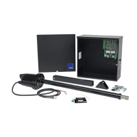
Visual identification of the control box, actuator, pivot arm, gate bracket, and bolt kit.
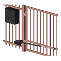
Instructions for locating the pivot point and setting the vertical position of the pivot arm.
Pivot arm placement, vertical position, and wiring for push-to-open configuration.
Steps and considerations for securely mounting the actuator to the pivot arm.
Recommendations for mounting the control box near the pivot arm and battery placement.
How to connect master and slave actuators to the control board and power.
Attaching the gate bracket to the extension tube and the gate itself.
Procedures for adjusting limit switches for the Model 1500 single gate operator.
Procedures for adjusting limit switches for the Model 1600 dual gate operator.
Explains the pinout for the 8-pin connector and various input terminals on the control board.
Configuration options via program switches for timer, sensitivity, and operation modes.
Details on adjusting timer, sensitivity, and information on control board fuses.
Instructions for connecting the Nice receiver to the control board terminals.
Steps for programming, deleting individual, and deleting all transmitters from memory.
Diagrams illustrating typical installation layouts for loop sensors and photocells for safety.
Recommended inspection schedule for battery, fire department equipment, gate, loops, and hardware.
Table listing common operational problems and their possible solutions.
Technical drawings showing the general dimensions of the control box.
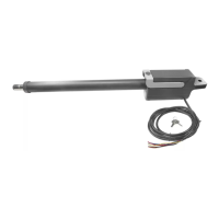
Technical drawings showing the general dimensions of the actuator in its closed state.
Lists and identifies components of the control box assembly, including cabinet, lid, tab, keyswitch, and circuit board.
Lists and identifies components of the actuator's front housing assembly.
Lists and identifies components of the actuator's back housing assembly.
Details the 2-year limited warranty, terms, conditions, and limitations of liability.
Checklist for installers and customers to ensure proper installation and acceptance.
| Model | Apollo 1500 |
|---|---|
| Remote Control | Yes |
| Warranty | 2 years |
| Power Source | Electric |
| Operating Temperature | -20°C to +55°C |