12
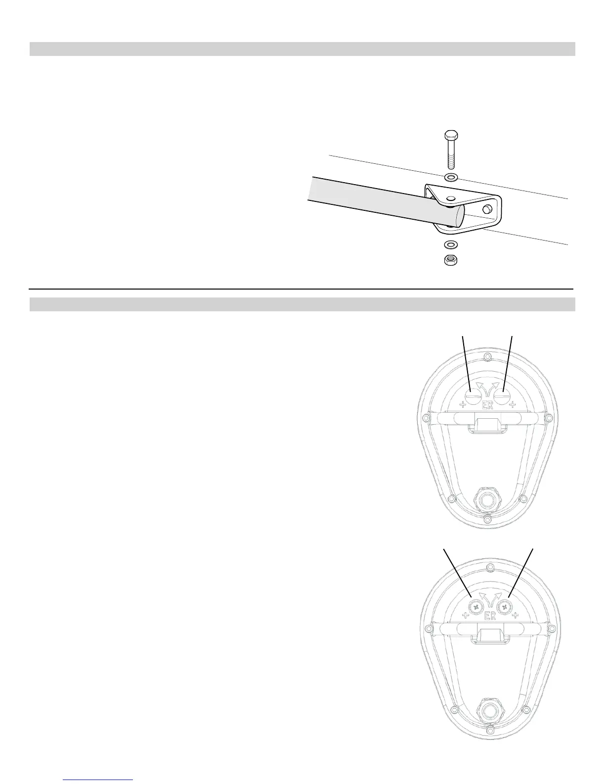
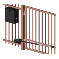
13 - GATE BRACKET MOUNTING
14 - LIMIT SWITCH ADJUSTMENT
Pull to Open only: Activate push button on the side of the control box and extend the actuator until it stops (leave actuator
retracted for PUSH TO OPEN).
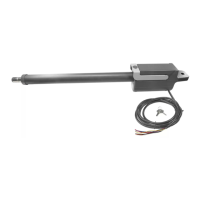
WARNING: Do not let extension tube rotate as it extends. Do not insert ngers or tools in the hole at the end of the
extension tube.
Connect the gate bracket to the end of the extension tube
with supplied 1/2” x 3” bolt. With the gate in the closed
position, place the gate bracket on the gate and mark
placement or secure with a clamp. Unbolt and remove
the extension tube from the bracket and weld or bolt the
bracket to the gate using 3/8” bolts, lock washers, and
nuts.
Bolt the actuator to the gate bracket as shown.
Tip: Tack weld or C clamp at rst if uncertain about location.
Run the unit through a complete cycle to insure proper
operation then mount permanently .
14.1 - Model 1500 (single gate operator)
Remove the limit screw end caps. A shown in the gure to the right.
With the gate in the closed position depress the LED ENABLE button on the
circuit board. You should see the MASTER CLOSE limit LED illuminate. Using
the black button on the side of the control box cycle the operator to the open
position. If the actuator does not stop before reaching the fully open position
depress the black button to stop the motor in the desired open position. Adjust
the retract (pull to open) or extend (push to open) limit as shown in the gure
below. Turn the limit correct screw until the MASTER OPEN limit LED illuminates
(while holding the LED enable button).
Do not extend the extension tube too far or you will risk unscrewing the tube
from the main drive screw.
*Maximum extension length is 66”*
EXTEND more: Turn the limit screw counterclockwise
EXTEND less: Turn the limit screw clockwise
RETRACT more: Turn the limit screw clockwise
RETRACT less: Turn the limit screw counterclockwise
Remove limit switch end caps
Extend limit screw Retract limit screw
14.2 - Model 1600 (dual gate operator)
Follow the steps above to set the master gate actuator while leaving the slave
gate actuator disconnected. Once the master gate actuator is set, disconnect the
master gate actuator and plug the slave gate harness into the master side of the
circuit board. Follow the same steps to set the limits on the slave gate actuator.
Once both actuators are set, plug the master gate actuator into the master side
of the board and slave gate actuator into the slave side of the board.
As you open and close the gates, you will notice that the slave side moves 2-3
seconds slower than the master. This is normal due to the length of cable on the
slave gate actuator.