13
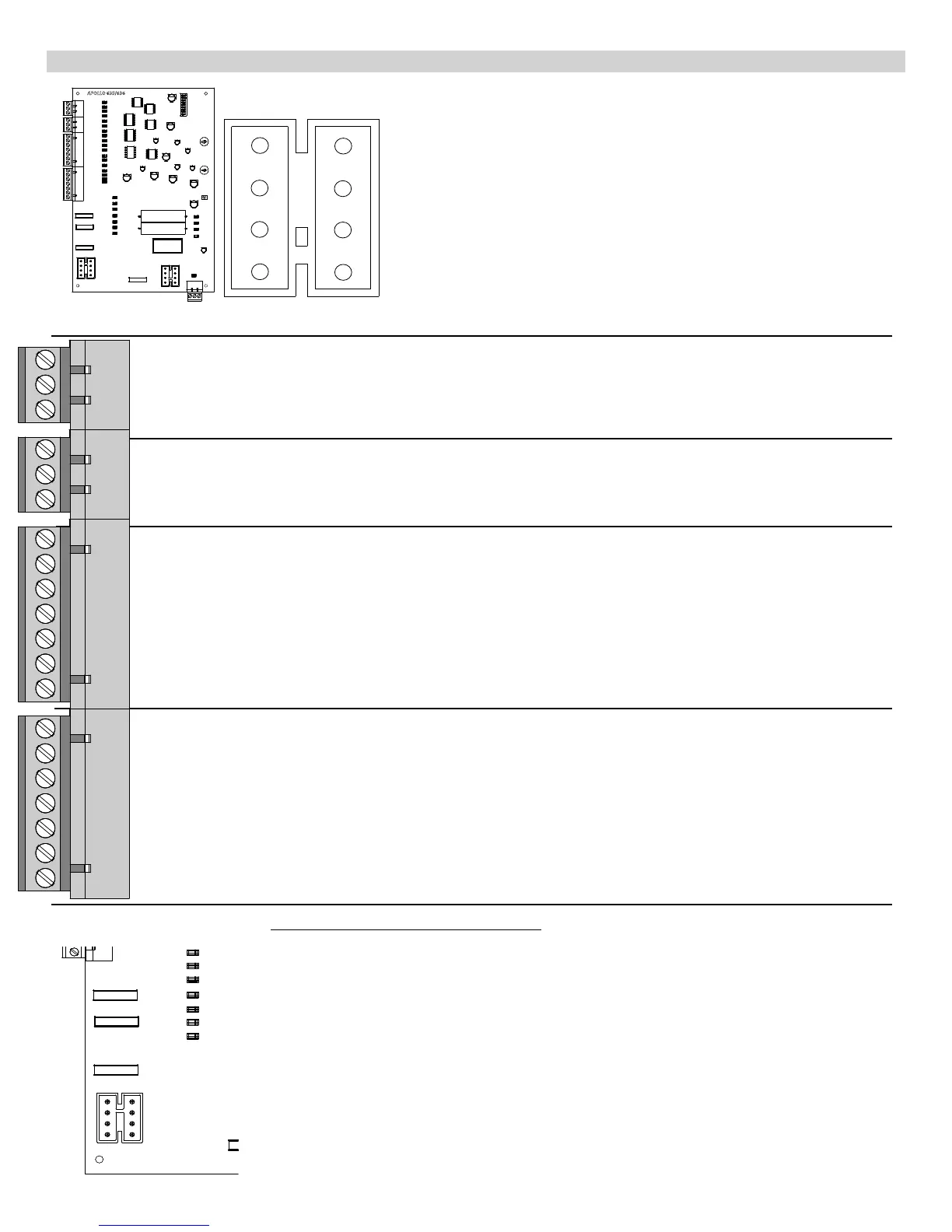
15 - 635/636 CONTROL BOARD CONNECTIONS
8 Pin White Connector (two on 636 Master & Slave)
1 ORANGE - Open Limit Input
(Normally open unless gate is opened)
2 WHITE - Close Limit Input
(Normally open unless gate is closed)
3 BLACK - Motor - Positive during open cycle, Negative during close cycle
4 RED - Motor - Negative during open cycle, Positive during close cycle
5 GREEN - Limit Switch Common
6 Not used
7 BLACK - Ground - Battery Negative
8 RED - Battery Positive (+12 VDC)
GND - Supplied Battery Ground
INP - Step by Step activation
12V - Supplied battery voltage (protected with 3AMP fuse)
GND - Supplied Battery Ground
INP - Step by Step activation
12V - Supplied battery voltage (protected with 3AMP fuse)
EDGE - Reverse edge input. Will stop and reverse gate if closing, resets close timer if gate is open.
EDGE - Reverse edge input. Will stop and reverse gate if closing, resets close timer if gate is open.
GND - Supplied Battery Ground
GND - Supplied Battery Ground
STOP - Stop input from a 3 button station
CLOSE - Close input from a 3 button station
OPEN - Open input from a 3 button station
GND - Supplied Battery Ground
GND - Supplied Battery Ground
FREE EXIT - Opens gate if closed, stops and reverses gate if closing, resets close timer if gate is open.
GND - Supplied Battery Ground
SHADOW - Resets close timer when gate is open (also referred to as under gate loop)
GND - Supplied Battery Ground
SAFETY - Resets close timer if gate is open, stops and reverses if gate is closing. Does not open a closed gate
Emergency Bypass Connector
Used when the control board is not functioning.
Located on the lower left corner of the circuit board.
Unplug the motor harness from the Master (or Slave) Connector and momentarily insert into
the Emergency Bypass Connector to open the gate. Make sure to unplug the connector from
the emergency bypass before the gate fully opens and binds. In the event the motor is not
disconnected quickly enough, the blue 15 amp fuse will protect the circuit board from damage
and should be replaced when the original problem is xed.